

Custom Search
|
|

|
||
 MIL-HDBK-1013/12
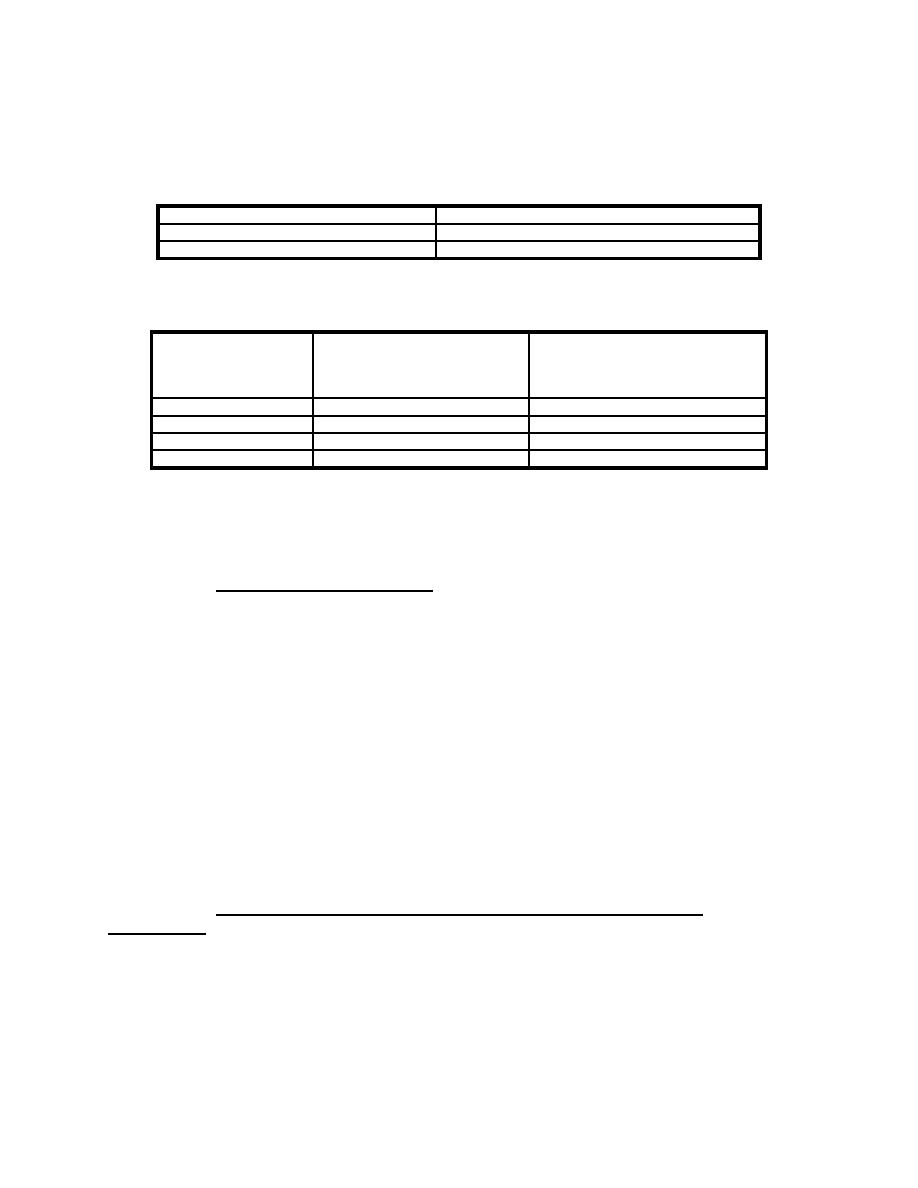
Table 6
Minimum Thicknesses for Ballistic Resistant Frames
Item
Minimum Size, inch (mm)
Frame Thickness
1/4 (6) steel
Removable Stop Thickness
3/16 (5) steel
Table 7
Minimum Thicknesses for Ballistic Resistant Walls
Reinforced Concrete
Threat Severity
CMU (grouted) or Brick
Thickness,
Level
Thickness,
3,000 psi (21,000 kPa),
inch (mm)
inch (mm)
Low
4 (100)
2 (50)
Medium
4 (100)
2-1/2 (64)
High
8 (200)
4 (100)
Very High
(a) or (b)
8 (200)
(a) 4-inch (100-mm) solid CMU, 3/4-inch (19-mm) rigid urethane, and
8-inch (200-mm) grout-filled CMU.
(b) 6-inch (300-mm) grout-filled CMU, insulation, 6-inch (300-mm)
grout-filled CMU.
5.3.1
Required Information. The following information is
required for a ballistic resistant glazing evaluation:
a) Ballistic Tactic Design Basis Threat (medium, high,
or very high). This information is determined using
Appendix D and is recorded on the Glazing System
Design Criteria Summary worksheet.
b) Cross-section ballistic resistance certification.
c) Cross-section thicknesses.
d) Frame ballistic resistance certification.
e) Frame properties. Refer to Section 2 for
descriptions of frame properties.
f) Worksheets (see Appendix B):
1) Cross-Section Evaluation (CSE)
2) Frame Evaluation (FE)
3) Wall Evaluation (WE)
5.4
Cross-Section Ballistic Resistant Thicknesses
Procedure. This procedure helps to evaluate the performance of
an existing glazing cross-section subjected to ballistic attack.
It provides a set of structures that step an analyst through the
process of getting cross-section thicknesses for glazings known
to resist specific levels of ballistic attacks. A process chart
50
|
 |
|
|
||


