

Custom Search
|
|

|
||
 MIL-HDBK-1013/12
Air Gap
1-15/16
Figure F-7
(19) LAMa SGb, 1/4 (6) AIR,
(49)
15/16 (24) LAM POLYc
1-3/8 (35)
Figure F-21
1/8 (3) SG, 3/4 (19) LAM AGd, 3/8
(10) POLY
Glass-Clad
1-3/8 (35)
1 (25) LAM AG, 1/4 (6) POLY
Figure F-22
Polycarbonate
1-1/2 (37)
1-1/8 (28) LAM SG, 3/16 (5) POLY
Figure F-23
1-5/8 (41)
1-1/8 (28) LAM AG, 3/8 (10) LAM
Figure F-24
POLY
Laminated Glass 2 (50)
2 (50) LAM AG
Figure F-29
a
Laminated
b
Strengthened glass
c
Polycarbonate
d
Annealed glass
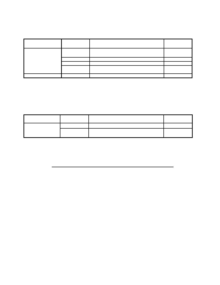
Table 11
Typical Thicknesses for Very High Threat Severity Level Ballistic Resistant
Glazing Cross-Sections
Type
Thickness,
Cross-Section,
Figure
inch (mm)
inch (mm)
Glass-Clad
2-1/16 (52)
Figure F-25
1-5/8 (41) LAMa AGb, 1/4 (6) POLYc
Polycarbonate
2-1/16 (52)
Figure F-26
1/8 (3) SGd, 1-1/8 (28) LAM AG,
3/16 (5) POLY
a
Laminated
b
Annealed glass
c
Polycarbonate
d
Strengthened glass
5.5
Ballistic Resistant Glazing Selection Procedure. This
procedure contains structures for analysis of glazing systems
subject to ballistics attack. This procedure will step an
analyst through the process of selecting cross-sections and
frames to protect against specific ballistic attack threat
severity levels. A process chart is shown in Figure 20 and a
description of the procedure is presented in Figure 21.
54
|
 
|
|
|
||


