

Custom Search
|
|

|
||
 MIL-HDBK-1013/12
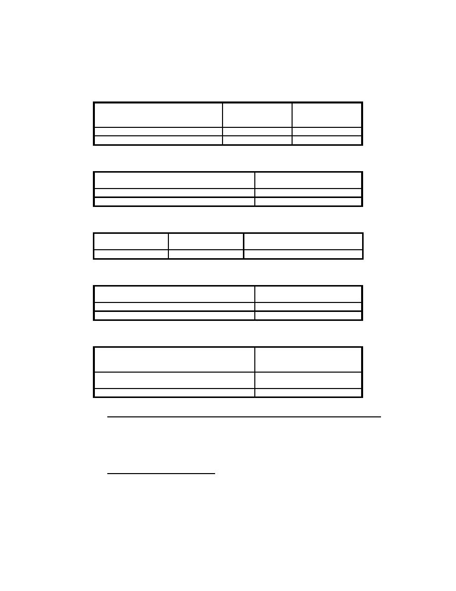
Table 23
Minimum Anchorage Size for Medium Threat Severity Level
Minimum
Anchor Bolt
Minimum
Embedment,
Diameter,
inch (mm)
inch (mm)
One-Piece Expansion Sleeve
1/2 (13)
3 (76)
Taper Bolt
3/8 (10)
3 (76)
Table 24
Concrete Anchor Bolt Maximum Spacing for Medium Threat Severity Level
Space
Maximum Spacing,
inch (mm)
Frame Corner to Bolt
6 (150)
Between Adjacent Bolts
12 (300)
Table 25
Removable Stop Anchorage Size for Medium Threat Severity Level
Bolt Type
Minimum Size,
Minimum Number Per Side
inch (mm)
Shouldered
3/8 (10)
2
Table 26
Removable Stop Bolt Spacing for Medium Threat Severity Level
Space
Maximum Spacing,
inch (mm)
Frame Corner to Bolt
9 (230)
Between Adjacent Bolts
18 (460)
Table 27
Minimum Wall Thicknesses for Medium Threat Severity Level
Wall Construction
Minimum Wall
Thickness,
inch (mm)
Reinforced Grout-Filled Concrete
8 (200)
Block
Reinforced Concrete
6 (150)
7.4
Forced Entry Resistant Glazing Evaluation Procedure.
This procedure aids an analyst by providing structures that step
through the process of evaluating a glazing system's performance
against forced entry attack. Figure 28 presents a process chart
and Figure 29 provides a description of the procedure.
7.4.1
Required Information. The following information is
required for a forced entry analysis for evaluation application:
71
|
 
|
|
|
||


