

Custom Search
|
|

|
||
 MIL-HDBK-1023/4
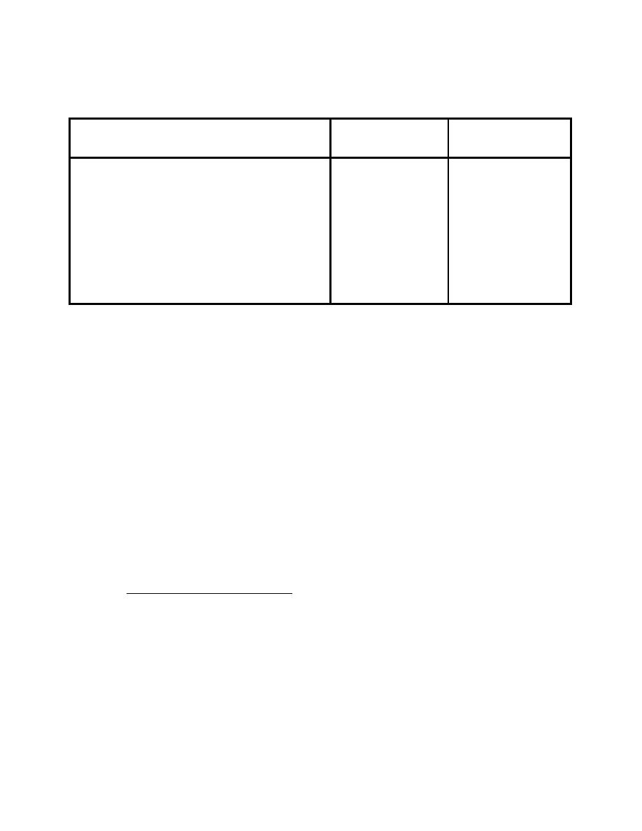
Table 10
Table of Insulation-Resistance Test Values for Field Circuits
First Test on New
Succeeding Tests and
Circuit
Old Circuits
Complete Approach System (5000V leads, 500
9000V
5000V
and 300W transformers)
Touchdown Zone and Centerline Light Circuits
9000V
5000V
(5000V leads, 200W transformers)
High Intensity Runway Edge Light Circuits
9000V
5000V
(5000V leads, 500 and 200W transformers)
Medium Intensity Runway and Taxiway Circuits
6000V
3000V
(5000V leads and 30/45W transformers)
600 Volt Circuits
1800V
600V
(10) Radio-Control of Airport Lighting. Check the operation of radio-controlled
airport lighting by keying a portable transmitter and observing the actuation of the switching
mechanism. If a fault is detected, follow the manufacturer's recommendation for repair or
replacement.
(11) Lightning Arresters. Check the lightning arresters for burning, scorching, or
other signs of failure. Lightning arresters should be inspected for damage after each lightning
storm in the area.
(12) Miscellaneous. Inspect all miscellaneous vault items, such as circuit breakers,
terminal blocks, potheads, vault lights, switches, etc. Make sure they are clean and all
connections are tight.
d) Annual checks
(1) Dielectric Checks. Perform dielectric tests on oil in oil-filled equipment such
as circuit breakers, regulators, and transformers as described in par. 5.6.1.
(2) Paint. Check the condition of the paint on the equipment and vault. Repaint as
necessary.
5.4.2
Recommended Vault Procedures
a) Airport Plan. An airport plan should be permanently posted in the vault to aid in
testing and troubleshooting the field circuit loops. This airport plan (preferably behind glass)
shows the field layout, marked with the location of all lights, cable runs, cable splices, and
lighted navigational aid equipment.
b) Schematic Diagram. Up-to-date diagrams of all power and control circuits should
be displayed in the vault. Both a schematic diagram, which is a symbolic depiction of the logic
of the circuit, and a wiring diagram, which is a detailed layout showing all wires and
connections, should be displayed.
44
|
 
|
|
|
||


