

Custom Search
|
|

|
||
 MIL-HDBK-1023/4
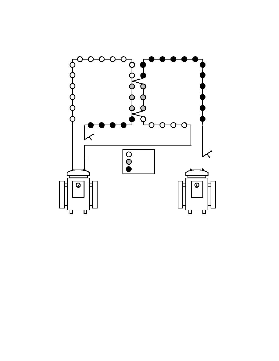
(4) Figure 36 illustrates the results of "Circuit Integration" on the two load-to-load
shorts. The actual shorts would be located in the area of the dim/off and dim/on light transition
in the loads.
L2-A
= ON
L2-B
L1-B
= DIM
= OFF
L1-A L2-A
L1-B L2-B
ON
OFF
A
B
REGULATOR
REGULATOR
HIGH VOLTAGES EXIST ON CABLES L2-A AND L2-B.
TAPE EXPOSED CONDUCTORS PRIOR TO ENERGIZING.
Figure 36
Two Load-to-Load Shorts - Circuit Integration Method
Caution: Never integrate a 20.0 ampere regulator onto a 6.6 ampere load. The 20.0 ampere
regulator will surely blow out all the 6.6 ampere lamps. If a 20.0 ampere load and a 6.6 ampere
load become shorted together, troubleshoot the circuit with the 6.6 ampere regulator. It will still
be possible to locate the short looking for the on/off transition.
In the case of Figure 36 with two load-to-load shorts, let's say regulator B is a 20.0 ampere
regulator and A is a 6.6 ampere regulator. The first thing that might need to be done is to replace
some lamps on load A if the 20.0 ampere circuit has been run. Then the test should be run as
illustrated. Identify the on/off or on/dim transition and locate one of the shorts, on that one side,
i.e., where the 6.6 ampere and 20.0 ampere circuits first merge. Next, disconnect the two load
101
|
 
|
|
|
||


