

Custom Search
|
|

|
||
 MIL-HDBK-419A
2.6.1.2 Other Commonly Used Electrodes. Table 2-5 lists a number of simple isolated earthing electrodes
along with approximate formulas for their resistance to earth. The plate and spherical electrodes are extensive
in area, whereas the vertical rod, the horizontal rod (or wire), the star, and the circle are extensive in length.
The electrodes in Table 2-5 have been ranked after being normalized for equal surface area in contact with the
earth. The order of ranking is such that the lowest resistance-to-earth electrode (the most effective) heads the
l i s t . As an example, a circular plate lying on the earth's surface is a more effective electrode (has a lower
resistance to earth) than a buried, horizontal rod which has the same area in contact with the earth, assuming
that the rod is buried at a depth less than 40 percent of its length.
The resistance to earth provided by horizontal conductors as a function of length is shown in Figure 2-9 for two
depths of burial. Note that as the length is doubled, the resistance is approximately halved. The curves of
Figure 2-9 assume that the conductors are laid out in a straight line. If the strips are coiled or curved, the
resistance tends to be higher because the cross-sectional area of the soil affected is less.
The resistance of a plate ground is dependent upon the area of the plate. The variation of resistance as a
function of the radius of a circular plate is illustrated in Figure 2-10 for three depths of burial. These curves
are calculated for a plate in soil of uniform resistivity of 10,000 ohm-cm. Similar relationships hold for
rectangular plates; the curves as shown should be considered to indicate the behavior of resistance as a function
of area rather than as a prediction of the resistance of plate of a given area.
2.6.2 Resistance of Multiple Electrodes. The theoretical resistance of an electrode, such as given by Equation
2-16, is obtained only at an infinite distance from the electrode. As shown in Section 2.6.1.1, however, most of
the resistance of a single electrode is obtained within a reasonable distance from the electrode. (For a vertical
rod, better than 90 percent is realized within two rod lengths.) If two or more electrodes are closely spaced,
however, the total effective resistance of neither is realized. This interaction prevents the resistance of N
electrodes connected in parallel from being l/N times the resistance of one of the electrodes. For this reason,
the crowding of multiple vertical rods is not as beneficial in terms of dollar cost per ohm as is achievable with
fewer rods properly spaced. If the electrodes in a multiple electrode installation are separated by adequate
distances, the interactive influence is minimized. The separation between driven vertical ground rods in a
group of rods should not be less than the length or greater than twice the length of an individual rod.
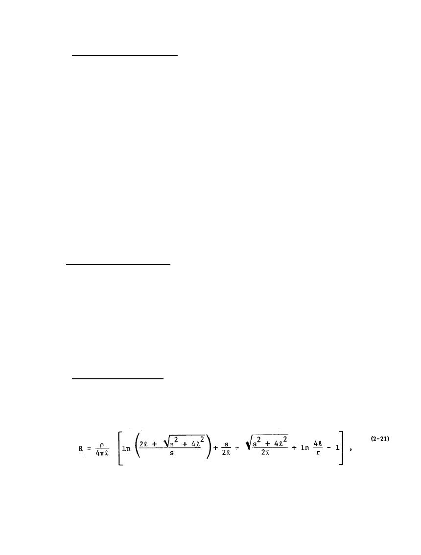
2.6.2.1 Two Vertical Rods in Parallel. Expressions for the resistance of multiple electrodes are more complex
than those for isolated electrodes. To illustrate, consider two rods driven into the earth with their tops flush
with the surface as shown in Figure 2-11. The two rods are electrically in parallel, but the presence of one rod
affects the resistance of the other. The resistance-to-earth of two rods (2-9) is
where s = spacing between rods.
2-23
|
 |
|
|
||


