

Custom Search
|
|

|
||
 MIL-HDBK-419A
2.6.2.3 Horizontal Grid (Mesh). Earth electrode subsystems for electric power stations and substations must
be designed both to provide low resistance to earth and to minimize voltage gradients at the earth's surface (see
Section 2.8.1). A common electrode design for such applications is a grid, or mesh, of horizontal rods or wires
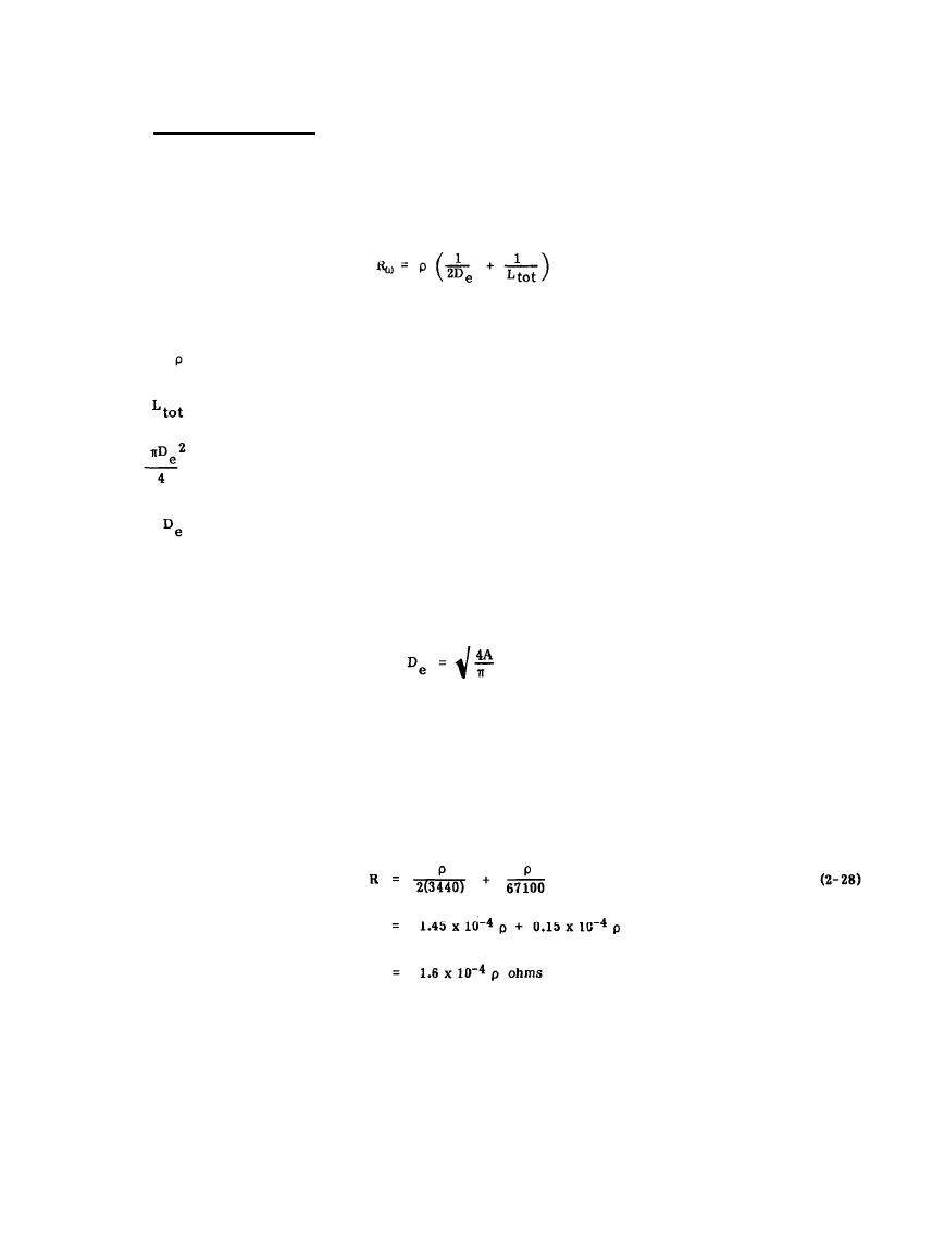
connected at each crossing. The resistance to earth for a square or a rectangular grid can be calculated from
the following Equation (2-3)
(2-27)
where
= earth resistivity,
= total length of conductors used,
= A = area covered by grid, and
= effective diameter of grid.
As an example, consider a square grid that has dimensions of 30.5 m x 30.5 m (100 feet by 100 feet) with
conductors spaced 3.05 m (10 feet) apart. Thus there are 100 meshes with a total conductor length of 670 m
(2200 feet). The area of the array is 929 square meters (10,000 square feet) with an effective diameter of
= 113 feet
= 3440 cm
Thus the resistance to earth, by Equation 2-27, is
2-29
|
 
|
|
|
||


