

Custom Search
|
|

|
||
 MIL-HDBK-419A
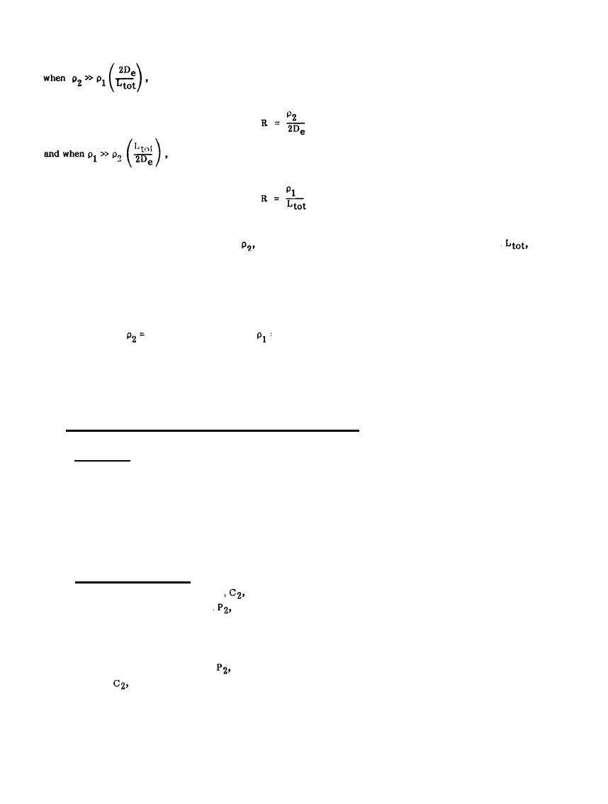
the earthing resistance is approximately
(2-37)
it is approximately
(2-38)
If, for example, the diameter, De, of the grid equals 500 meters, the resistivity, pl, of the superficial layer
of the subsoil equals 200 ohm-meters, and the length,
of
equals 10,000 ohm-meters, the resistivity,
the conductors in the grid equals 4,000 meters, then
R = 2.7 ohms
Burying the grid within the lower resistivity subsoil would reduce the resistance-to-earth to about 0.4 ohms.
Conversely, if the
10,000 ohm-meters, and
= 200 ohm-meters, then
R = 10 ohms
regardless of the depth of the grid.
2.7 MEASUREMENT OF RESISTANCE-TO-EARTH OF ELECTRODES.
2.7.1 Introduction. The calculated resistance of a given electrode system is based on a variety of assumptions
and approximations that may or may not be met in the final installation. Because of unexpected and
uncontrolled conditions which may arise during construction, or develop afterward, the resistance of the
installed electrode must be measured to see if the design criteria are met. In an existing facility, the
resistance of the electrode system must be measured to see if modifications or upgrading is necessary. Two
commonly used methods for measuring the resistance to earth of an electrode are the triangulation method and
the fall-of-potential method.
2.7.2 Fall-of-Potential Method. This technique involves the passing of a known current between the
electrode under test and a current probe,
as shown in Figure 2-15(a). The drop in voltage between the earth
electrode and the potential electrode,
located between the current electrodes is then measured; the ratio of
the voltage drop to the known current gives a measure of the resistance. (By using a voltage measuring
device - a null instrument or one having a high impedance - the contact resistance of the potential electrode
will have no appreciable effect on the accuracy of the measurement.) Several resistance measurements are
taken by moving the potential probe,
from the position of the earth electrode, along a straight line to the
which is left in position. The data obtained is then plotted as resistance versus distance
current probe,
from the earth electrode as illustrated in Figure 2-15(b). This is the test method recommended for
measurement of single rod or multi-rod earth electrode subsystems.
2-35
|
 |
|
|
||


