
Custom Search
|
|

|
||
 MIL-HDBK-419A
2.8.1.2.3 Buried Horizontal Grid. An expression for the resistance to earth for a buried grid was presented in
Section 2.6.2.3. Equations 2-27 and 2-28 are the sum of a resistance of a superficial plate
and a
resistance term representing the per unit diffusion resistance of the earth electrode material
A voltage
which is proportional to the per unit average current flowing from the conductors of the mesh into the
earth represents an approximation of the potential difference between the conductors of the mesh and the
center of the open space with each mesh. The sketch of Figure 2-23 shows the resultant voltage distribution
across a section of a grid. Note that the approximation used here would predict that
(2-65)
is the minimum voltage (with respect to infinity) at the edge of the grid, so that the grid simply translates the
dangerous voltage gradient to the periphery of the grid (2-3).
If the value of earth resistivity is moderately high--say
ohm-cm--and if the lightning current is 2 x
amperes, the grid in the example of Section 2.6.2.4 would exhibit
(2-66)
= 3000 volts
over a five-foot (1.5 m) distance. This would exceed the safe step voltage of 1000 volts, developed earlier.
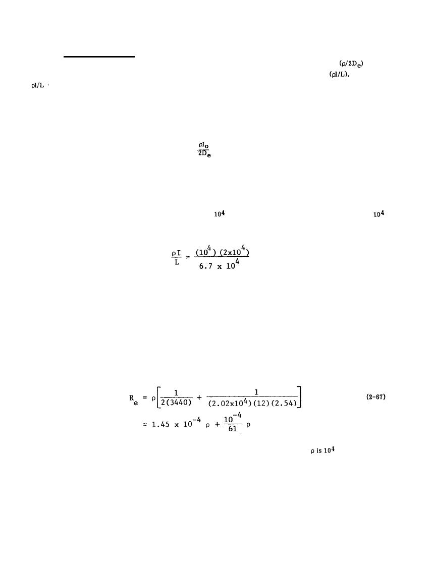
If the grid is made of conductors spaced one foot apart for a total conductor length of 20,200 feet (6157 m)
there would be 10,000 meshes on the 10,000 square foot (929 m2) area. The effective diameter would still be
113 feet (34.4 m), and the computed resistance would be
The maximum step potential difference over the grid of the latter case, again assuming
ohm-cm and an
effective lightning current of 20,000 amperes, would be
2-55
|
 
|
|
 |
||