

Custom Search
|
|

|
||
 MIL-HDBK-419A
6.3.1 Basic Theory of Common-Mode Coupling.
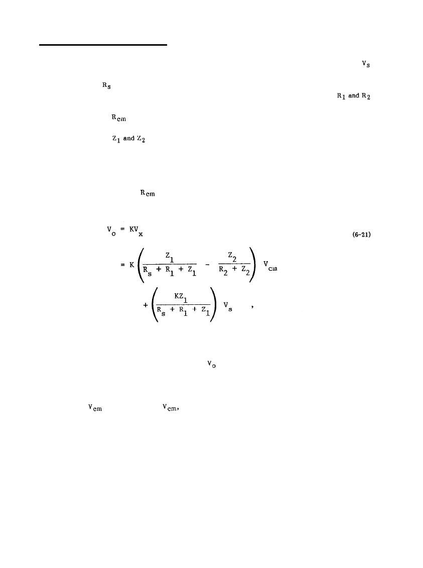
The mechanism of common-mode coupling can be explained with reference to Figure 6-14. In this figure,
represents some signal voltage from an unbalanced source, i.e., the output signal of some transducer or
measuring amplifier, and
is the output impedance of this source. The source is connected to the input
terminals of some electronic device which is modeled as a two-terminal pair amplifier in the figure.
are the series resistances in the interconnecting cables between the source and amplifiers. The voltage source
represents a common-mode noise voltage source which causes the signal
c
source to be at some voltage when measured with respect to the ground reference of the amplifier output. In
Figure 6-14, the impedances
represent the input impedances of the two amplifier terminals. In a
differential amplifier, these impedances are normally very high, however, in a single ended amplifier, one is
high and the other is very low since it is tied directly to the ground reference terminal.
The analysis of the circuit in Figure 6-14 is complicated enough to make it difficult to reach conclusions
is small and can be neglected. With this approximation, it can be
without excessive algebra. Normally,
shown that the output voltage of the amplifier is given by
where K is the voltage gain of the amplifier.
in Equation 6-21: the desired signal and the
There are two signal contributions to the output signal
undesired common-mode noise. There are three ways in which the common-mode noise term can be reduced.
These are as follows:
the common-mode noise voltage at the output terminals
Decrease
- By decreasing
a.
decreases proportionally.
6-19
|
 
|
|
|
||


