

Custom Search
|
|

|
||
 MIL-HDBK-419A
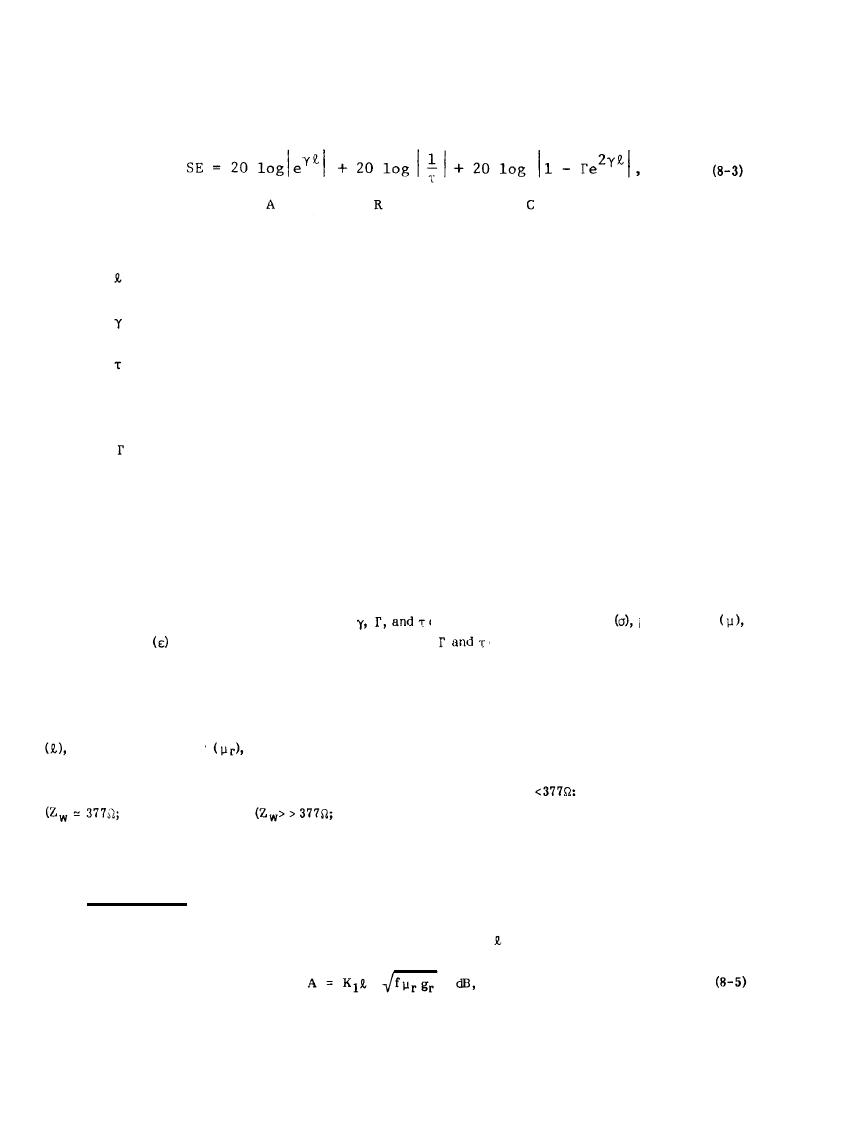
The shield effectiveness (in decibels) of a large, plane sheet of metal with an EM wave arriving along a path
perpendicular to the sheet has been shown (8-2) to be:
where
= thickness of the shield,
= propagation constant of the shield,
= transmission coefficient,
and
= reflection coefficient.
The shielding equation is often written as
SE = A + R + C
(8-4)
where A, R, and C are the indicated three terms in Equation 8-3 and represent respectively the Absorption
Loss, the Reflection Loss, and the Correction Term for re-reflections as discussed earlier. In a particular
shielding application, the values of the constants
depend upon the conductivity
permeability
of the shielding material. The values of
depend also upon the wave impedance of
and permittivity
the EM wave impinging upon the shield.
For convenience in the use of the shielding effectiveness equation, the individual terms A, R, and C have been
expressed in more readily usable forms as functions of the EM wave's frequency (f) and of the shield's thickness
relative permeability
and conductivity relative to copper (gr). Simplified approximate expressions
have been derived for the reflection and correction terms. The selection of the appropriate approximate
expression will depend upon whether the wave impedance is low (Zw <
magnetic field), medium
electric field). Low impedance fields are found in the proximity
plane wave), or high
of loop antennas, high impedance fields are found near dipole antennas, and plane waves exist away from the
near fields of source antennas.
8.3.1 Absorption Loss.
The absorption loss of an EM wave passing through a shield of thickness
can be shown (8-2) to be given by:
8-5
|
 
|
|
|
||


