

Custom Search
|
|

|
||
 MIL-HDBK-419A
and f are as defined with Equation 8-8. The plane wave reflection loss is seen to decrease as the
where
wave frequency increases, and to be better for shielding materials with lower ur/gr ratios. Figure 8-7 shows
the plane wave reflection loss as a function of frequency for iron, copper, and aluminum shields. The curve for
iron, unlike those for copper and aluminum, is not a straight line because iron's relative permeability is
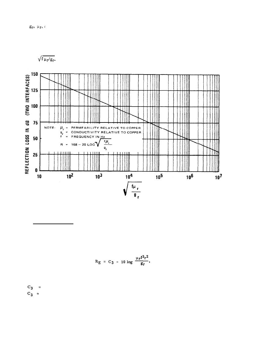
frequency dependent. Figure 8-8 provides a universal curve for plane wave reflection loss as a function of the
parameter
Figure 8-8. Universal Reflection Loss Curve for Plane Waves (8-3)
8.3.2.3 High Impedance Field.
The EM field in the proximity of an electric dipole antenna has a high electric field-to-magnetic field strength
ratio (high wave impedance). The reflection loss for such a field encountering a shield is given by
(8-10)
where
322, if r is in meters
354, if r is in inches,
8-15
|
 
|
|
|
||


