

Custom Search
|
|

|
||
 MIL-HDBK-419A
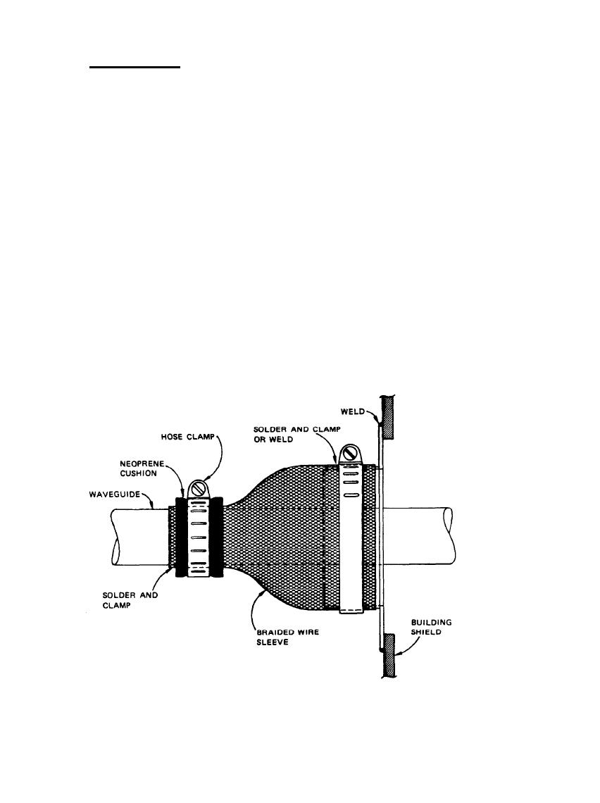
10.4.2.4.2.2 Braided Wire Sleeve.
A somewhat less effective, but usually adequate attachment to the waveguide can be made with a braided wire
sleeve. As illustrated in Figure 10-14, the braided wire sleeve is necked down and soldered to the waveguide
and flared out over a collar on the facility shield wall, where it is also soldered or welded. For mechanical
strength, both of these attachments should be reinforced with a hose clamp and cushion, as was used with the
rigid sleeve. And as with the rigid sleeve, the clamp may be used without solder at the waveguide if soldering
cannot be tolerated, but, as before, both the braid and the waveguide must be clean when assembled and remain
clean after assembly.
The braided wire sleeve must expand into a large enough hoop to enable the waveguide end fittings to pass
through (unless the sleeve is installed before the fittings are installed). In addition, it is desirable that the
sleeve have an optical coverage of at least 85%. Thus, the sleeve design is fairly stringent because large
expansion is usually accompanied by low coverage.
For both the bellows and the braided wire sleeve attachments, it is recommended that the attachment
mechanism be placed inside the facility wall and that a weatherproof boot or other external seal be installed to
keep moisture and other foreign matter out of the attachment.
Figure 10-14. Braided Wire Sleeve Clamped to Waveguide
10-23
|
 
|
|
|
||


