

Custom Search
|
|

|
||
 MIL-HDBK-419A
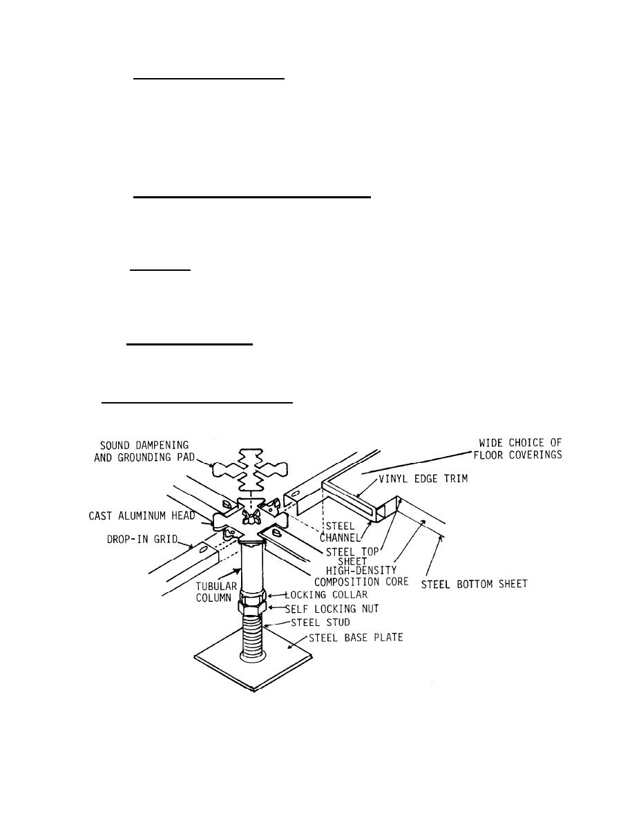
1.5.1.1.1.4.2 Drop-In or Removable Grid System. The Drop-In Grid System is shown in Figure 1-62. The grids
or stringers are retained by engaging pins or depressions in the pedestal head. The stringers supply support and
when newly installed provide comparatively low resistance contact to the pedestal head. Equipment cabinets
resting on the floor panels provide increased contact pressure in certain areas. Severe corrosion and unreliable
electrical contact have resulted due to dirt, moisture and floor cleaning/waxing compounds filtering through
crevices. This floor system is also considered unsuitable for a reference plane. Floor panels resting on the
pedestals and grids are commonly 24" x 24" although they may be purchased in 30" x 30" dimension.
1.5.1.1.1.4.3 Free-Standing, Pedestal-Only or Stringerless System. The pedestal-only system is shown in
Figure l-63. The pedestal base is glued or "shot" in place to form the basic understructure. The pedestal heads
are leveled and the floor panel is installed. The conductivity between distant pedestals is variable and
unreliable, making it unsuitable for a ground reference.
1.5.1.1.1.5. Ground Risers. The type of ground riser to be used depends on the type of equipotential plane to
be installed and whether the subject building will be new construction, a major modification to an existing
building in which new equipments will be installed, or an existing building in which only the ground system will
be upgraded while the equipments remain in place. The latter case is discussed in Section 2.2.3.
1.5.1.1.1.6 Equipment Cabinet Grounding. Each individual unit or piece of equipment should either be bonded
to its rack or cabinet (see Figure 1-64), or have its case or chassis bonded to the nearest point on the
equipotential plane. Racks and cabinets should also be bonded to the nearest point of the plane.
1.5.2 Lower Frequency Signal Reference Network. Lower frequency signal reference subsystems are not to be
installed in communications-electronics facilities.
Figure 1-62. Example of Drop-In Grid Floor Construction
1-131
|
 
|
|
|
||


