
Custom Search
|
|

|
||
 MIL-HDBK-419A
1.8.3 Selection of Materials. The selection of a shielding material can be done either by (1) choosing a possible
metal of a given thickness and then determining if the shielding effectiveness is equal to or greater than the
field attenuation desired, or (2) starting with desired attenuation, determining what thickness of metal sheet or
what type of screen is required. Either approach is acceptable.
a.
As the first step in the selection of a shield type and material, ascertain the nature of the field by
determining whether it is an electric field, magnetic field, or a plane wave. (The distance between the source
and the shield relative to signal wavelength gives an indication of the impedance characteristics of the incident
field. Note the source may be either the actual signal generator such as a transmitter or it may be the
current-carrying conductor such as a power line or signal cable.)
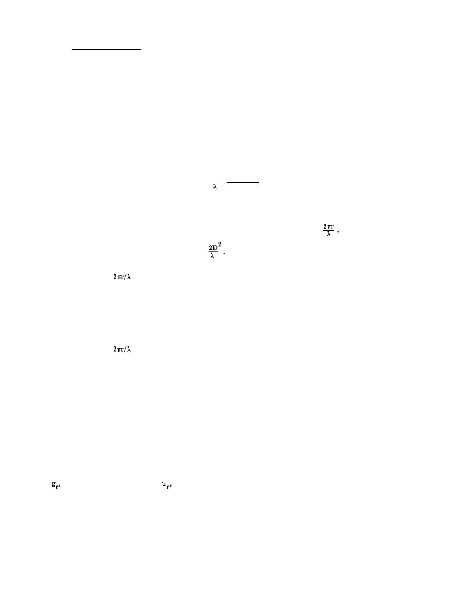
First compute the wavelength, λ, or the incident signal or signals from
(1)
8
3 x 10
=
f
For f in hertz, λ will be in meters.
(2)
If source location is known, measure or estimate r. Then calculate
r is distance from source in meters
Value of r must be greater than
D is length of antenna in meters
(3) If
is less than unity, the incident field will either be a high impedance electric field or it
will be a low impedance magnetic field. To determine which one, try to establish what type of source produced
the field. (An electric field source is characterized by a high source impedance and relatively low currents.
Examples are high voltage dc power supplies; static discharges; short monopole antennas; etc. A magnetic field
source is generally characterized as a low impedance, high current source. Typical magnetic sources are loop
antennas and power lines.)
(4)
If
is unity or greater, assume the incident field is a plane wave.
Next, use Figure 1-85 to obtain the absorption loss of the material selected for a plane wave. To
b.
use this nomograph, draw a straight line between a point on the right hand vertical scale that corresponds to the
particular metal involved and the correct point on the thickness scale (center scale on the nomograph). Mark
where the straight line crosses the unlabeled pivot line. Next place a straight edge between the marked point
on the pivot line and the frequency of interest (left most vertical scale). Read the absorption loss off the
compressed scale just to the left of the thickness scale. (The determination of the absorption loss of a 14 mil
sheet of stainlesssteel at 1 kHz is illustrated on the figure. First, line 1 is drawn between stainless steel on the
right hand scale and 14 mils on the thickness scale. Then line 2 is drawn between 1 kHz on the left hand scale
and the crossover point. The indicated absorption loss is 3 dB.)
If the specific metal of interest is not indicated on the right hand scale, obtain both the relative conductivity,
from Table 1-29. Multiply gr times ; use the product as the right hand
, and the relative permeability,
location for line 1 and complete the determination. (Given the frequency and the desired absorption loss, this
nomograph can be used to determine the thickness and/or the type of metal needed.)
1-160
|
 
|
|
 |
||