

Custom Search
|
|

|
||
 MIL-HDBK-419A
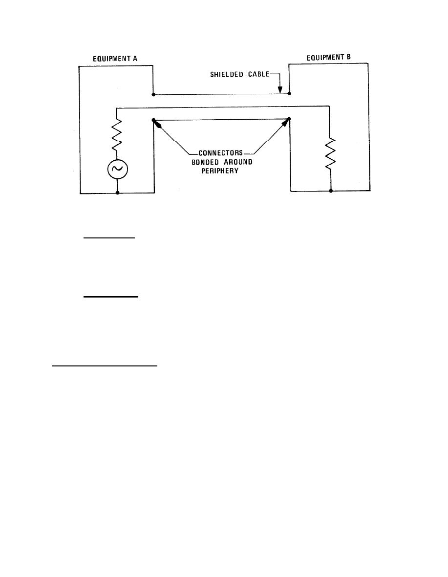
Figure 3-9. Establishment of Shield Continuity Between Higher Frequency Equipments
3.2.1.2.1 Signal Interfaces. For higher frequency signals, the interfacing lines between equipments may be
unbalanced, constant impedance, transmission lines such as coaxial cables. The current return conductor, e.g.,
the shield in the case of a standard coaxial cable,* should be grounded to the equipment enclosure at both ends
of the cable and at intermediate points along the cable run. (This multiple-point grounding of the shield
maintains the rf shielding effectiveness of the cables and simplifies equipment design.)
3.2.1.2.2 Cable Connectors. Cable connectors must have less than one milliohm contact resistance to provide
a low impedance path between the cable shield and the equipment case on which the connector is mounted.
Bond the shield completely around its periphery of the cable to the connector shell with a tight compression or
soldered bond. Soldered connections are preferred over clamps. Higher frequency shield terminations must
maintain the rf-tightness of the interconnected system (see Figure 3-9).
*In low level, wideband (particularly video) systems, noise voltages arising from stray power currents (or from
currents induced in cable shields by incident rf fields, i.e., the antenna effect), flowing through the cable shield
can be troublesome. A way to combat the rf pickup problem is to, in effect, enclose the shield carrying the
signal return current inside of another shield or use a balanced type of transmission line. To accomplish the
first of these alternatives, either a triaxial type cable can be used or the coaxial cable can be routed in metallic
conduit. The inner shield of the triaxial cable or the shield of the conduit-protected coaxial cable should be
terminated to the signal ground on the inside of the equipment. The outer shield of the triaxial cable and the
conduit should be peripherally bonded to the case or cabinet of the terminating equipments. If the interference
is the result of stray power currents, the current path through the shield must be interrupted or a twinaxial type
of cable must be used. To interrupt the path for stray power currents, the system's signal reference must be
connected to structure at only one end. Thus, either the source or load end signal reference must be isolated
from structure and the ac ground. The isolation can be effected either by floating the equipment or its internal
circuitry. Generally, however, either process is very difficult to implement and maintain and it is preferable to
resort to a balanced interface or locate the source and reduce the magnitude of the stray current.
3-13
|
 
|
|
|
||


