

Custom Search
|
|

|
||
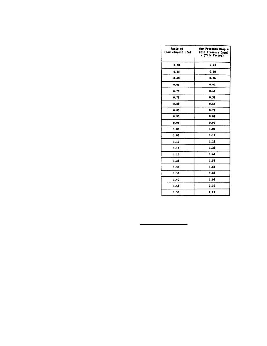 TABLE 2-2
Table 2-2 may be used to solve the same problem.
Static Pressure
Simply divide the new desired cfm by the existing
Increase/Decrease
cfm to determine the ratio in the first column.
Read in the second column, the appropriate factor
to be multiplied by the original pressure drop.
Once the pressure drop is known for a system
at any given airflow, the pressure drop for any
other airflow may be calculated using the method
above. When the pressure drop and airflow are
plotted on a graph for a number of different
airflows, we have created a system curve. The
original pressure drop for a given airflow may be
arrived at by measurement of the existing
system. For a system yet to be installed, the
designer must calculate what the friction losses
will be in order to determine the total pressure
loss. Calculation of these pressure losses will
be explained later in this chapter.
2.5 FAN TYPES.
The two general categories of
fans are:
Centrifugal
a.
b.
Axial
The centrifugal fan (Figure 2-6) consists of
an impeller and a housing. The overall direction
of airflow is perpendicular to the direction of
the fan shaft. Air is drawn into the center of
the impeller and discharged through the housing.
The fan may have the inlet on just one side; a
double fan width may be used with inlets on both
sides. These two arrangements are commonly called single width single inlet
(SWSI) or double width double inlet (DWDI).
The impeller is driven through a direct drive or belt drive
Direct drive fans, with the motor housing inside the impeller
arrangement.
(Figure 2-7), are sometimes referred to as squirrel cage fans.
There are several different designs in use for the centrifugal fan
impeller. They are:
Forward curved (FC)
1.
Backward inclined (BI)
2.
3.
Airfoil (AF)
4.
Radial
The blade configuration for each of the impeller types is shown in
Figure 2-8. Of all the different designs, the FC fan is by far the most
commonly used in residential and commercial applications. For a given cfm
requirement, the FC fan will be the smallest wheel, and will operate at the
lowest rpm, The FC wheel is used where the static pressure requirements are
moderately low (up to 2 to 3 inches water column). The forward looking cup
of the FC wheel can become filled with dirt, and reduce the fan's effective-
ness. This is not a problem in clean applications.
2-6
|
 
|
|
|
||


