

Custom Search
|
|

|
||
 In Figure 2-28, a duct system is shown with both velocity and static
pressure. The velocity in the duct connected to the suction side of the fan
is the same as the velocity in the discharge duct. Therefore, the velocity
pressure would be the same everywhere in this duct system. However, the
static pressure is different everywhere along the length of the duct
system. Just as the air enters the suction duct, the static pressure would
be very close to zero (atmospheric pressure). Just at the suction side of
the fan, the static pressure would be the lowest of anyplace in the system.
At the discharge side of the fan, the static pressure would be the highest,
and it would gradually be reduced until just before the end of the discharge
duct, the static pressure would once again be zero. When measuring airflow
in ducts, we must make sure that we account for the effects of static
pressure, which are independent of the effect of velocity pressure.
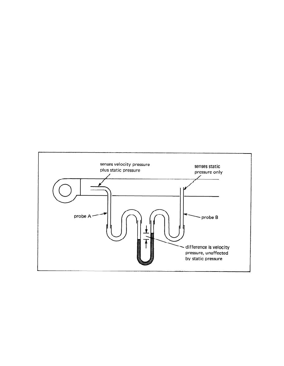
Consider the duct probes shown in Figure 2-28. Probe A is facing into
the direction of airflow and senses both velocity pressure and static pres-
sure. Probe B has an opening perpendicular to the direction of airflow. It
is unaffected by velocity and it senses static pressure only. When we
connect these two probes to the manometer as shown, the reading will
correspond to the velocity pressure only. Regardless of the static
pressure, the same static pressure acts on both legs on the manometer, and
each cancels the effect of the other.
FIGURE 2-28
Velocity Flow Measurement in Duct
2-27
|
 
|
|
|
||


