

Custom Search
|
|

|
||
 TM 5-683/NAVFAC M-116/AFJMAN 32-1083
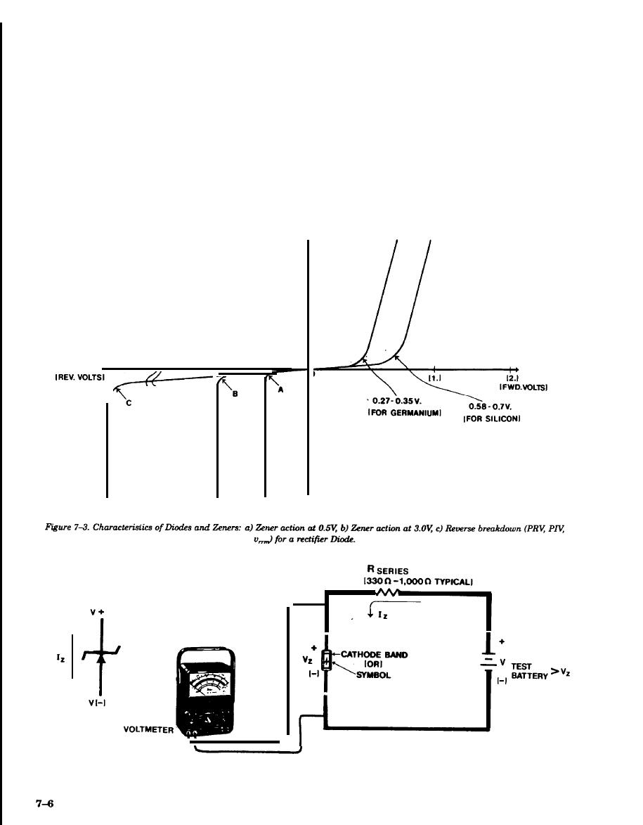
sired breakdown voltage in the reverse direction.
ode, but especially Zener diodes, should be operated
The Zener diode will provide rectification in its for-
with some means of external series resistance in
ward mode; however, the precise voltage developed
order to limit the maximum current flow to within
across its reverse junction is of greater interest.
the rating of the device. The Zener diode can be
This property is useful as a voltage reference. No
manufactured to produce reverse breakdown
significant reverse current flows until the Zener
(Zener) voltages from 0.5-100.0 volts or more with
voltage (V) is reached. At this point, a sharp in-
power ratings from 025W--100W. The Zener diode
crease in reverse current occurs as illustrated in
is teated like the general purpose rectifier diode;
figure 7-3 characteristics "A" and "B". The device
however, its Zener voltage (V) cannot be determined
will maintain its voltage over a considerable range
using the ohmmeter tests. An external test voltage
of reverse current. It should be noted that any di-
must be applied to determine V (fig 7-4).
FWD.
CURRENT
-550V. . . -1OV.
-3V.
-0.5V.
I
REV.
CURRENT
Figure 7-4 Testing Zener Voltage.
|
 
|
|
|
||


