

Custom Search
|
|

|
||
 TM 5-683/NAVFAC MO-116/AFJMAN 32-1083
which prevents damage to the meter in this situa-
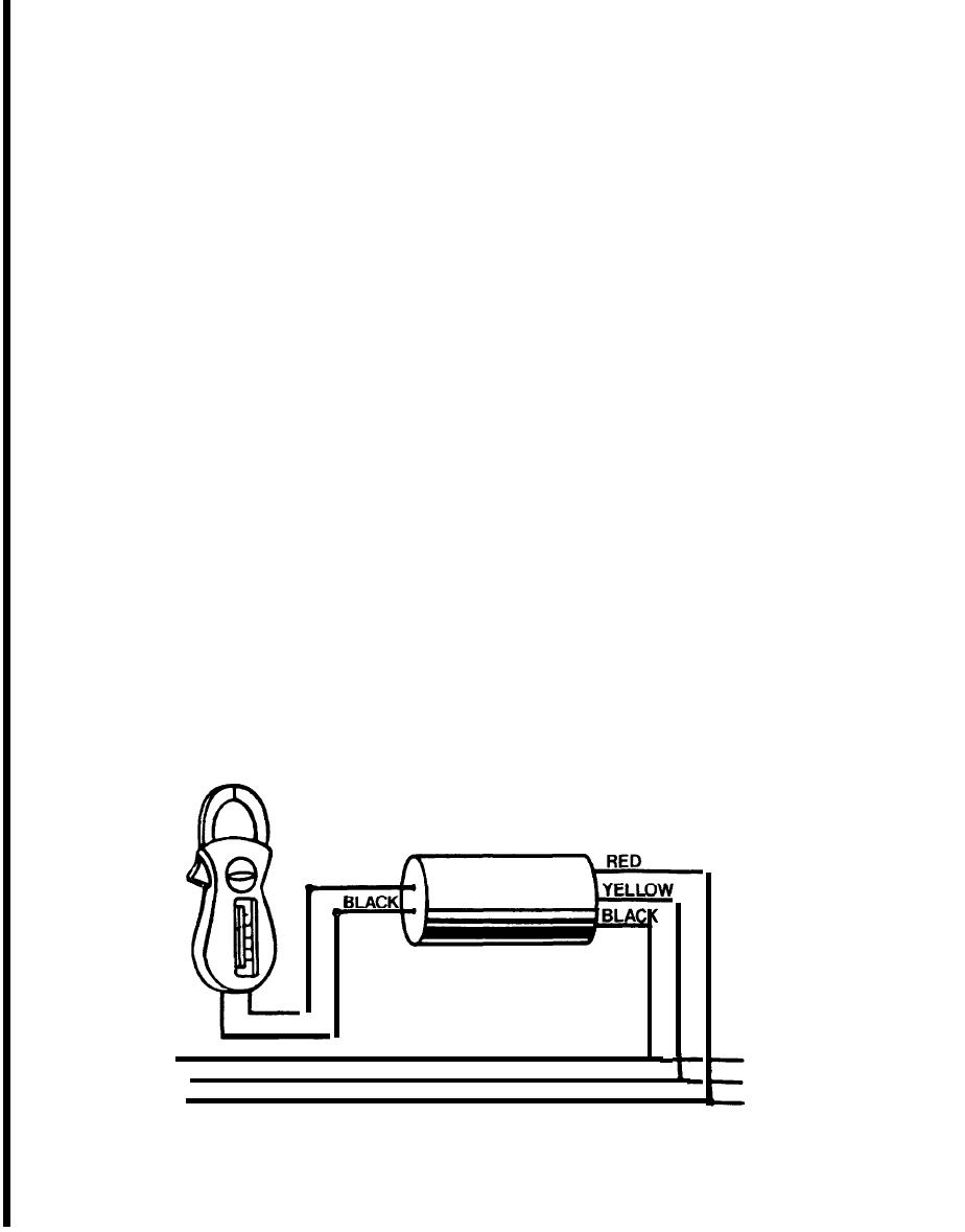
used in conjunction with the voltmeter circuit of the
tion. If a resistance is connected across the termi-
clamp-on volt-ammeter. To determine phase se-
nals, current flows through coil A, R' and the un-
quence, the circuit voltage is first measured. Then
known resistance Rx. This current attempts to
connections are made as shown in figure 13-3. If the
move coil A clockwise, but the opposing force created
meter reading is higher than the original circuit
by current through coil B tries to move it counter-
voltage, the phase sequence is black-yellow-red. If
clockwise. The final position of the coils is deter-
the meter reading is below original circuit voltage
mined by the magnitude of the current through Rx'
the phase sequence is red-yellow-black.
and the coils will stop at a point where the forces
13-4. Megohmmeter.
tending to move them are at a balance. The pointer
then indicates the value of the unknown resistance
The megohmmeter is an instrument used to meas-
on the scale. No springs are used in the movement
ure very high resistances (fig 13-4). The megger
since the opposing forces in coils A and B balance
consists of a hand-driven direct-current generator
the pointer when a reading is being taken. Having
and a meter to indicate resistance in ohms. The
no springs to hinder its movement, the pointer
meter used is an opposed coil type, having two coils,
floats freely back and forth across the scale when
A and B, mounted over a gapped core (fig 13-5). The
the meter is not in operation. Megohmmeters may
coils are wound on a light frame, and rotate around
be obtained with different voltage ranges; the more
the core which remains stationary. The current for
common being 500 and 1000 volts. The higher the
the coils is supplied by the hand-driven generator.
To explain the operation of the unit, it is necessary
resistance range to be measured, the higher the
voltage required to actuate the movement for read-
to exam ne the action of the coils with the earth and
i
lien terminals open; with these terminals shorted;
to its rated voltage output. In operation, these
and with a resistance (Rx) across these terminals.
clutches are designed to slip if cranked over a cer-
When these terminals are open, current flow is from
tain rate of speed, thus dropping the output to a
the generator, through B and R which are in series
safe value.
with the generator. Since the terminals are open, no
a. Safety precautions. When operating a
current flows through coil A to oppose movement
megohmmeter, a very high voltage is generated at
and coil B will swing counterclockwise to a position
the output terminals which could prove fatal. The
over the gap in the core. In this position the pointer
following safety precautions should be adhered to
indicates infinity. With the terminals shorted to-
when operating a megohmmeter.
gether, a larger current flows through coil A than
through coil B and the greater force in coil A moves
(1) Take the equipment to be tested out of ser-
vice. This involves de-energizing the equipment and
the pointer clockwise to the zero position on the
disconnecting it from other equipment and circuits.
scale. Resistor R' is a current limiting resistor
BLACK
PHASE SEQUENCE ADAPTER
- VOLTAGE LEADS
3 PHASE LINE
Figure 13-3. Setup for testing phase sequence.
13-6
|
 
|
|
|
||


