

Custom Search
|
|

|
||
 TM 5-683/NAVFAC MO-116/AFJMAN 32-1083
Table 14-1. Interpreting insulation resistance test results.
WHAT TO DO
CONDITION
No cause for concern.
1. Fair to high values and well-
maintained.
Locate and remedy the cause and check
2. Fair to high values, but
the downward trend
showing a constant tendency
towards lower values.
Condition is probably all right, but
3. Low but well-maintained.
cause of low values should be checked.
Clean, dry-out, or otherwise raise the
4. So low as to be unsafe.
values before placing equipment in
service (test wet equipment while
drying out).
5. Fair or high values,
Make tests at frequent intervals until
previously well-maintained,
the cause of low values is located and
but showing sudden lowering.
remedied; or until the values have
become steady at a lower level but safe
for operation; or until values become
so low that it is unsafe to keep the
equipment in operation.
to be applied to each particular relay, and the test
points. This data is often furnished on a time-
current characteristic curve of a coordination study.
(4) A test instrument should be available as
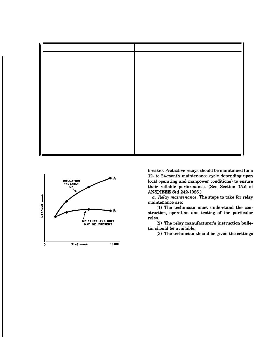
Figure14-3. Typical curves showing dielectri absorption effecting
recommended by the manufacturer.
a time-resistance or double-mading test.
(5) Most protective relays can be isolated for
testing while the electrical system is in norma op-
14-3. Protective relay testing.
eration. However, an operation of the breaker is
Protective relays are used to detect and isolate sys-
required to ascertain that the operation of the relay
tem abnormalities with minimum disturbance to the
contacts will trigger the intended reaction, such as
rest of the electrical distribution system. The more
to trip the associated circuit breaker.
common protective relays are the electro-mechanical
b. The tests to be performed are determined by
types. In them, a mechanical element, such as an
the relay to be tested. For electro-mechanical re-
induction disk or magnetic plunger, moves in re-
lays, inspection, testing and adjustment are recom-
sponse to an abnormal change in a parameter of the
mended.
eletrical system. This movement causes a contact in
(1) Inspection. Each relay should be removed
the control circuit to operate, tripping the circuit
from its case for a thorough inspection and cleaning.
14-3
|
 
|
|
|
||


