

Custom Search
|
|

|
||
 TM 5-684/NAVFAC MO-2OO/AFJMAN 32-1082
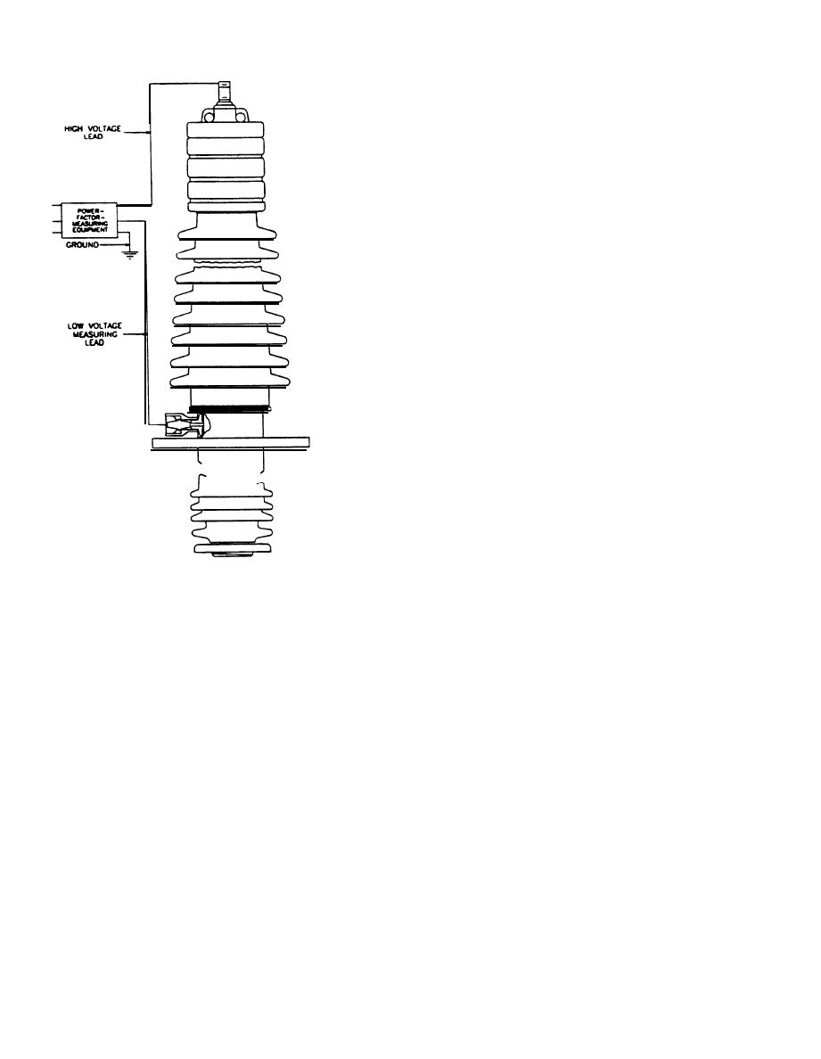
conducting rubber or metallic foil or braid collar
around the porcelain under the first top skirts; con-
necting the collar to the test cable guard circuit;
grounding the mounting flange; and applying test
voltage to the central conduct of the bushing. The
collar should be of a type specifically designed for
bushing collar tests. Figure 3-2 shows connections
for hot- and cold-collar tests.
(1) Hot-collar test. This test is performed by
grounding the central conductor and the mounting
flange and applying test voltage to the collar on the
bushing. When hot-collar losses are found to be high
because of high relative humidity creating surface
leakage, the bushing should be cleaned. Furniture
or floor wax should be applied with a clean lintless
cloth. The wax should dry for 5 minutes and then be
rubbed briskly with a clean cloth to obtain a high
polish.
(2) Cold-collar test. This test is performed by
grounding the collar and mounting flange and ap-
plying test voltage to the central conductor of the
bushing. The difference between the overall watt
loss and the cold-collar loss is known as watts dif-
ference. In general, there appears to be no advan-
tage in the cold-collar test. The hot-collar test is
recommended.
j. Interpretation of power factor test results. The
--
limiting value at which different test operators re-
move bushings from service ranges from 6 to 12
percent power factor on bulk-type bushings and
from 2 to 6 percent on plastic and oil-filled bush-
Figure 3-l. Connections for ungrounded specimen power
ings. These ranges are based on bushing tempera-
factor test
tures of 68 degrees F (20 degrees C), the power
(3) Connect the high-voltage lead of the power fac-
factor values being higher at higher temperatures.
tor test set to the top terminal of the bushing and the
Because the measurement of power factor is highly
low-voltage lead to the bushing support.
specialized and power factor values vary with differ-
(4) Ground the test set to the apparatus tank, and
ent types and makes of equipment, the procedure
measure the power factor
following such tests should be based on the recom-
(5) Record temperature of the bushing.
mendation of the qualified persons engaged to per-
h. High-voltage cold-guard circuit test. When
form the tests.
bushings to be tested have detachable cable conduc-
tors, they may be tested in the following manner:
3-35. Bushing insulation resistance test.
(1) Remove the bushing terminal and insulate
Insulation resistance tests measure insulation
the conductor from the bushing tube by stuffing a
losses by applying a dc voltage. This test is not so
small amount of insulation into the space between
widely used as the ac power factor test for bushings;
them. If bushing is equipped with an insulating
but, in the absence of facilities to test power factor,
head, it is only necessary to remove the connector
insulation resistance tests on bushings may prove
between the upper and lower rings.
useful.
(2) Clean the porcelain ring of the insulating
a. Procedures. The general procedure for insula-
head.
tion resistance testing is described in chapter 5,
(3) Connect the guard circuit to the cable lead
section VII. The following paragraphs contain spe-
and the high-voltage lead of the test set to the bush-
cific details for testing bushings.
ing tube.
b. Test values. See table 3-4 for requirements for
(4) Ground the mounting flange of the bushing.
insulation test values. Resistance readings should
i. Collar tests. The overall power factor test on
be carefully compared in one or two ways.
bushings may be performed by placing a flexible
3-12
|
 |
|
|
||


