

Custom Search
|
|

|
||
 TM 5-684/NAVFAC MO-200/AFJMAN 32-1082
OF LEAD
WIRE
STAPLE
T E N SIO N S T R A N D
(CUT
INSTALLATION)
360 K
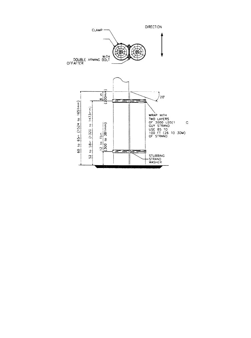
Figure 4-7. Wood stub pole
c. Compound set methods. There are a number of
also contain an approved preservative additive that
compound set methods. Engineering evaluation
migrates to the outside surfaces of the pole under a
should select the appropriate method.
time-delay release action.
(1) Compound. The simplest method requires a
(3) Compound, rebars, and collar. This method
compound (mixed in a completely self-contained
requires a 2-foot (0.6-meter) deep trench to be exca-
mixing unit) which fills a hole slightly larger than
vated around the pole and several 4-foot (1.2-meter)
the pole diameter. It is suitable also for straighten-
long rebars to be stapled about the pole. An inert 3
to 4 foot (0.9 to 1.2 meter) collar descends to about 2
ing poles.
(2) Compound and casing. The decaying region
feet (0.6 meters) below the ground line and is filled
by funnel with hand or electric mixed epoxy-resin
is first treated with a liquid fumigant. A split-metal
compound. Periodic tamping is needed to ensure
casing is driven below grade by rotary-driven equip-
proper compound setting. The trench is then
ment. The casing is filled with an epoxy-aggregate
backfilled after the compound has cured.
for stabilization and extra strength. The filler may
Section V - CROSSARMS, BRACES, AND PLATFORMS
4-19. Pole crossarms.
ments should be kept tight. If preservative treat-
ment is applied to the pole, the crossarms should
All facility crossarms are fully treated and are usu-
also be treated. Crossarms should be inspected vi-
ally of Douglas fir or yellow pine. The length and
sually from the ground whenever a pole is in-
cross section of an arm is determined by the brace
spected. If the pole inspection indicates the pole
and strength requirements. Properly installed cross-
may be climbed, a closer inspection should be made.
arms require little maintenance. Crossarms can de-
a. Decay. Crossarm decay usually starts at pin-
cay; aging can cause separations such as checks or
holes and can best be detected with a probe, if war-
shakes; lightning can splinter crossarms; or they
ranted by visual inspection. Probe the arm enough
may twist or bend by overload. These occurrences
may necessitate replacement. All crossarm attach-
to determine the extent of the decay.
4-11
|
 
|
|
|
||


