

Custom Search
|
|

|
||
 TM 5-684/NAVFAC MO-200/AFJMAN 32-1082
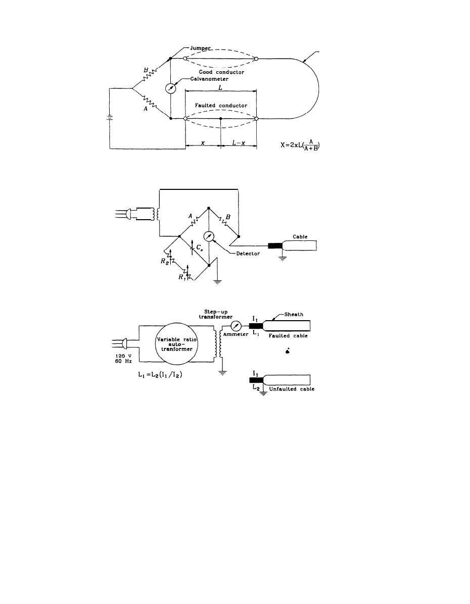
`Jumper
Point of
fault
Murry loop bridge method
120 v
60 Hz
Capacitance bridge measurement method
C h a r g i n g current method for fault location
Figure 5-l. Terminal equipment and cable connection diagrams
cable propagation velocity "v" multiplied by "t" and
current capacitance bridge is suitable, provided it
divided by two which results in equation 5-l.
measures capacitance to ground.
c. Charging current method. In the absence of an
(eq. 5-1)
d = vt/2
alternating-current bridge, the charging current on
(1) Distance determination. The TDR/analyzer
the faulted conductor and on a good conductor may
measures the reflection time and the fault distance
be compared, using several hundred volts or even
is automatically calculated based on the entered
several thousand volts at 60 hertz as the voltage
velocity of the pulse travel which is usually the ratio
supply. This circuit with its fault distance formula is
of the cable's propagation factor to the speed of light
shown in figure 5-1.
or a value of less than one. The analyzer can deter-
d. Time domain reflectometer (TDR) method. This
mine whether the fault is open-circuited or short-
method is based upon the measurement of the time
circuited based on waveform reflections as shown in
"t" it takes a generated pulse to reach a fault and be
figure 5-2.
reflected back. The fault distance "d" equals the
5-8
|
 
|
|
|
||


