

Custom Search
|
|

|
||
 TM 5-684/NAVFAC MO-200/AFJMAN 32-1082
Open
the
cable
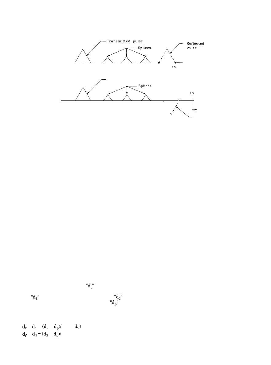
Transmitted pulse
Short
the cable
A
1
\
\
\
Reflected
pulse
Figure 5-2. Cable fault waveform reflections
5-17. Tracing the cable fault signal.
(2) TDR test settings. Tests require selecting a
pulse duration and a propagation factor.
A halving procedure can be used to trace faults
(a) Pulse duration. The pulse duration must
where the signal cannot be traced along the entire
be wide enough to be interpreted by the TDR ana-
length of the cable in any other way. It is time
lyzer and at least about one percent of the transit
consuming and costly, and more modern methods
time for the entire length of the tested cable. TDRs
utilizing the sophisticated signalling instruments
should have provisions for changing the pulse width
available should always be applied if possible.
depending on cable length.
a. Procedure. The procedure consists of localizing
(b) Propagation factor. This is the velocity of
the fault by progressively limiting it to one half of
the pulse in an insulated cable and will vary in-
the previously considered length of cable. The
versely as the square root of the product of the
points along the cable route chosen for signal mea-
cable's line constants, that is, its inductance and
surement must be selected so that maximum fault
capacitance. Therefore it will vary dependent upon
localization results from each and every measure-
cable insulation. A propagation factor of 500 feet
ment. Thus, the first measurement should be made
(152 meters) per microsecond for medium-voltage
as close to the midpoint of the circuit as possible;
cables or 600 feet (183 meters) per microsecond for
the second at the one-quarter or three-quarter
low-voltage cables is sufficiently accurate when
point, depending on the fault location given by the
fault distance measurements are made by two-end
first measurement; and so on.
fault pin-pointing.
b. Drawbacks. This procedure requires cutting
(3) Two-end fault pin-pointing. A propagation
the cable. For cable in duct an access point is
factor set to any value (which must remain un-
needed, or the duct line must be broken and a new
changed for both measurements) can be used to
structure provided for resplicing. For direct-burial
provide a TDR-measured fault distance from each
systems good cable will need to be respliced in a
end of the tested cable. These two distances will
new splice box. Resplicing can introduce other pos-
either come short of meeting or overlap each other.
sible trouble points.
The true distance to the fault
can be calculated
5-18. Selecting cable fault locating methods.
by equating the determined fault distance from end
one
to the fault distance from end two
and
The fault locating method differs dependent upon
the distance between these two points
using
the way the cable is installed. Most installations
equations 5-2 and 5-3, respectively, based on
will be in duct lines, but direct-burial and subma-
whether the determined fault distances fall short or
rine cable installations must also be considered.
overlap.
a. Duct line. The fault-locating equipment used is
=
+
+
(d, +
generally a tracer type. Pinpointing of the fault be-
tween structures is unnecessary. The entire length
=
+
(d, + d,)
5-9
|
 
|
|
|
||


