

Custom Search
|
|

|
||
 TM 5-684/NAVFAC MO-200/AFJMAN 32-1082
the values compared either on a voltage or a time
age is left on for 5 minutes and the leakage current
basis for initial to steady-state values or for a con-
is read after 30 seconds, 1 minute, and then at 1
stant rate of leakage current.
minute intervals thereafter up to 5 minutes. The
(1) Initial leakage current. The initial leakage
leakage current is plotted against time as the initial
current upon a test voltage application will include
high value reduces to a steady-state value. A con-
transient capacitive charging and dielectric absorp-
tinuous decrease indicates a good cable. There
tion currents. Two other currents, corona current
should be no increase in current during this period.
and surface leakage current, can be bypassed by
f. Test for cable withstand strength. A go/no-go
installing correct guarding circuits.
test is usually performed after repair if only cable
(2) Steady-state leakage current. The initial
withstand strength requirements need be verified.
value will decrease to a steady-state value consis-
The test provides a rising voltage up to the specified
tent with the system's charging current. If correctly
value applied to maintain a constant leakage cur-
done, only the volumetric leakage current will be
rent. A period of 1 to 1.5 minutes for reaching the
left. This current is of primary interest in the evalu-
final test voltage is usually adequate. The final test
ation of an insulation's condition. The decay of tran-
voltage is held for 5 minutes. If the current has not
sient current time is known as the stabilization
increased sufficiently in that time to trip protective
time.
devices, the cable withstand voltage is adequate.
(3) Constant leak age current. In some cases, a
constant leakage current is measured. This is main-
5-29. Cable power factor tests.
tained by increasing the test voltage in a manner
Power factor testing is a nondestructive ac test
which maintains the same current.
which has been utilized for many years to measure
e. Tests for relative cable condition. Two tests are
or test the integrity of substation insulation sys-
used to determine the relative cable condition as an
tems including cables.
identification of its dielectric strength under
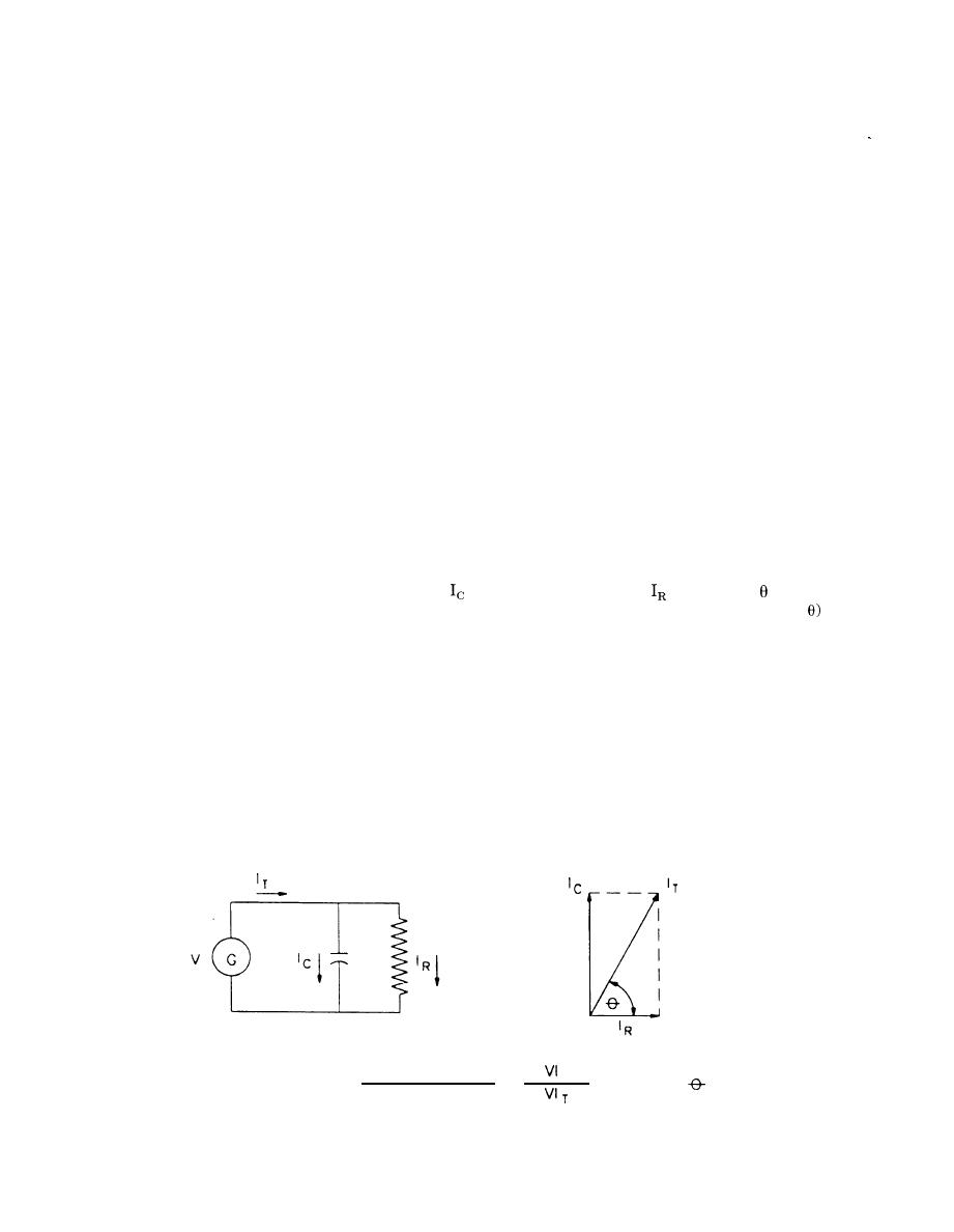
a. Test theory. An insulation to which voltage is
medium-voltage tests.
applied will act like a resistor and capacitor in par-
(1) Leakage current versus voltage test. In this
allel as shown in figure 5-3. The capacitive current
test, equal voltage steps are applied until the maxi-
will be much larger than
so the angle will be
mum test voltage is reached or an indication of a
close to 90 degrees and the power factor (cosine of
breakdown voltage is indicated. It is usually recom-
will be very small.
mended that no less than five and, if possible, eight
b. Cable power factor test limitations. Cable insu-
equal steps be made with no less than 1 and up to 4
minutes stabilization time allowed. The steady-
lation can be considered to consist of a simple ele-
ment of capacitance in parallel with resistance as
state leakage current is plotted against the applied
voltage. As long as the slope of the plot is the same,
shown in figure 5-3. The measured power factor is
the average of the entire length of the cable. If a
the insulation is in good condition. If the leakage
current increases noticeably, so will the slope of the
section of cable increases in power factor the high
value obtained for that section will be averaged
curve. Any change in the slope indicates that any
with the normal value obtained for the remainder of
voltage increase may cause insulation breakdown
the cable. The influence that the defective section of
and the test should be stopped.
(2) Leakage current versus time test. This test
the cable has on the overall cable power factor de-
pends on the relationship of the defective section
is made after the maximum test voltage of the pre-
length to the overall cable length. Thus, the ability
vious test has been determined. The maximum volt-
WATTS
R
.
POWER FACTOR=
= COSINE
VOLTAMPERES =
Figure 5-3. Insulation power factor equivalent circuit and vector diagram
5-16
|
 
|
|
|
||


