

Custom Search
|
|

|
||
 TM 5-684/NAVFAC MO-200/AFJMAN 32-1082
sary. Auxiliary reference grounds and test instru-
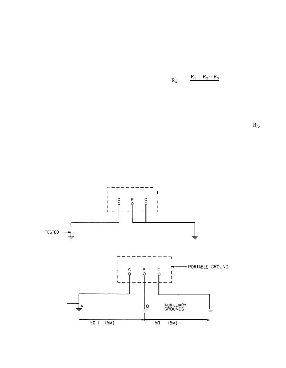
This arrangement is shown in figure 10-3. The
ground rods should be driven 8 to 10 feet (2.5 to 3
ments are necessary for ANSI/IEEE 80 and
meters) into the earth and spaced not less than 50
ANSI/IEEE 81 methods.
a. Minor grounding installations. The following
feet (15 meters) apart. Three separate tests are
made to determine the resistance of each of the
methods are suitable for measuring the resistance
series circuits when composed of only two grounds.
of isolated ground rods or small grounding installa-
The unknown resistance may then be calculated as
tions. Precision in measurements is difficult to ob-
follows by equation 10-l.
tain. Normally an accuracy of 25 percent is suffi-
cient, since the surrounding soil will not have
+
consistent values of temperature, moisture, and
=
(eq. 10-l)
2
depth.
(1) Portable ground testing instruments. A
Actual resistances may be determined by using one
of the following methods.
usual way to measure the ground resistance is with
(a) AC voltmeter-ammeter method. The con-
a low-range, self-contained, portable earth-tester in-
nections for the ac voltmeter-ammeter test are
strument such as the "Megger" Ground Tester or
shown in figure 10-3. The resistances of the ground
Ground Ohmer. The manufacturers' instructions
circuits are determined from the meter readings
should be followed in the use of this instrument.
and these values are then used in calculating
The two most common methods of measuring the
ground resistance with this type of instrument are
the direct-reference or two-point method shown in
the test current, if present, will introduce some er-
figure 10-l and the auxiliary ground method shown
ror in measurements.
in figure 10-2.
(b) DC voltmeter-ammeter method. A dc
(2) Three-point method. The three-point
voltmeter-ammeter method may also be used to de-
termine the resistance of each pair of grounds in
method of measuring ground resistance requires
series. Like the ac method, it is limited to locations
two auxiliary grounds, similar to those required
where power is available or where a battery source
with portable ground testing equipment, except
may be used with the regulating apparatus re-
that each auxiliary ground should have a resistance
quired to control the current flow. The line supply-
approximately equal to the ground being tested.
1
r-PORTABLE GROUND
R E S I S T A N C E MEASURING
INSTRUMENT
G R O U N D TO
-WATER
BE
SYSTEM
(LOW RESISTANCE)
Figure 10-l. Direct-reference or two-point ground test
I
RESISTANCE MEASURING
INSTRUMENT
,
GROUND TO
C
BE TESTED
fT(
MINIMUM
fT(
MAXIMUM
Figure 10-2. Auxiliary ground method
10-3
|
 
|
|
|
||


