

Custom Search
|
|

|
||
 TM 5-684/NAVFAC MO-200/AFJMAN 32-1082
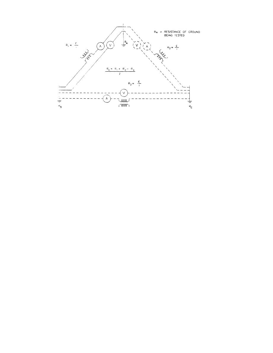
Figure 10-3. Ground resistance measurement, three-point method
tion of these methods may be necessary. Also see
ing the current must be free from grounds to mini-
IEEE 142 for additional information on the effect of
mize the effect of cross-currents. To compensate for
these changes.
the effect of stray dc voltage currents in the area,
a. Adding rods. An easy and preferable method of
readings should be made at both polarities.
b. Major grounding installations. Where accurate
reducing the resistance is to provide more rods. For
example, two ground rods, properly spaced and con-
measurements of extensive low-resistance ground-
nected in parallel, should have a combined resis-
ing systems are required, more elaborate test meth-
tance on the order of 60 percent of the resistance of
ods and equipment are needed using considerably
one rod; and for three rods, 40 percent of that resis-
larger separation distances between test electrodes.
tance. In general, proper spacing of rods means
Normally large facility substations are tested with
placing rods at least one rod length apart.
the fall-of-potential method in accordance with
b. Increased rod length. Providing longer rods is
ANSI/IEEE 81 requirements. Figure 10-4 shows a
particularly effective where low-resistance soils are
field setup for this method and the ground resis-
too far below the surface to be reached with the
tance curve. The resistance shown on the flat part of
normal rod lengths of 8 to 10 feet (2.5 to 3 meters).
the curve is taken as the resistance of the ground.
The amount of improvement from longer rods de-
The self-contained earth tester instrument shown
pends on the depth of the low-resistance soils. A
should be used rather than a voltmeter-ammeter
rather sharp decrease in the measured resistance is
combination, as the earth tester is designed to
usually noticed where the rod has been driven to a
eliminate the effects of stray currents. The primary
low-resistance soil level. Soil resistivity usually (but
advantage of this method is that potential and cur-
not always) decreases with depth because there is
rent electrodes (probes) may have substantially
normally an increased moisture content.
higher resistance than the ground system being
c. Soil treatment. A method called salting has tra-
tested without significantly affecting the accuracy
ditionally been used to treat the soil around ground
of the measurement.
(1) Major substations. To allow for seasonal
rods.
variations it is recommended that tests be made at
(1) Sodium chloride, calcium chloride, magne-
the same time each year or for each season of the
sium, and copper sulfate are all used as treatment.
year to allow for accurate comparison.
Bentonite, a natural clay, works well, except in a
(2) Procedures. Tests should be performed in
very dry environment. A pre-packaged mixture of 75
accordance with written procedures. Provide ad-
percent gypsum, 20 percent bentonite, a 5 percent
sodium sulfate. is recommended. Ground rods can
equate safety precautions as all electrical conduct-
also be encapsulated in concrete rather than using a
ing paths for overvoltage and fault currents are
connected to the substation grid.
soil treatment.
(2) Soil treatment is a reliable and effective
10-9. Method of reducing ground resistances.
method for reducing ground resistance and is par-
ticularly suitable for improving a high-resistance
Ground tests may indicate that the ground resis-
soil. The treatment is advantageous where long
tance exceeds safety requirements. Adding rods, in-
rods are impractical because of rock strata or other
creasing rod lengths, soil treatment, or a combina-
10-4
|
 
|
|
|
||


