

Custom Search
|
|

|
||
 TM 5-684/NAVFAC MO-200/AFJMAN 32-1082
j. Test equipment. Commonly used test equip-
every 6 months; however, more frequent inspections
may be desirable where unusual conditions prevail.
ment includes multirange ac and dc ammeters and
i. Solid-state devices. Because of the nature of the
voltmeters, timers, ohmmeters, and auxiliary re-
parts used (resistors, reactors, capacitors, trans-
lays. Test leads, resistors, and tool kits are also
formers, transistors, and integrated circuits), little
required for servicing controls. A suitable shop
maintenance is required. Inspection and testing are
should be available when major repairs are to be
done at comparatively long time intervals. Transis-
made. If solid-state equipment is to be checked, an
tors and integrated circuits are usually replaceable
oscilloscope or oscillograph and a high resistance
items and need little servicing. Many control parts
voltmeter will be required.
are similar to those used in magnetic controls, such
k. Repair parts. Spare parts should be kept on
as cases, bases, terminals, wiring, and conduit de-
hand, particularly if the equipment cannot be taken
vices. Standard magnetic control items, such as
out of service for long periods of time. Parts should
fuses, switches, contactors, overload devices, and
be stocked if they receive considerable wear or ex-
some relays, may be used in conjunction with solid-
perience frequent replacement. A list of spare parts
state devices. The infrequent operation of controls
from the appropriate manufacturer can be used as a
used in starting and stopping operations may lead
general guide for stocking. When broken or dam-
to special maintenance problems. Inspections every
aged parts are returned to the manufacturer, they
6 months should be satisfactory, unless this period
should be accompanied with complete information
exceeds manufacturers' recommendations.
regarding model number, nameplate data, duty
(1) Characteristics. Ambient temperatures, vi-
cycle, service conditions, description of the failure,
bration, electrical noise, surge currents, and tran-
and probable reasons for the failure.
sient overvoltages, in excess of those specified by
the manufacturer, can cause unacceptable affects.
11-12. Troubleshooting controls.
Always check that system characteristics do not ex-
ceed the requirements stated in the manufacturers'
In order to expedite repair work, it is important
instructions.
that the technician be thoroughly familiar with the
(2) Precautions. Polarized devices connected in-
equipment and the control operation. An elemen-
correctly may malfunction and damage the equip-
tary wiring diagram is most useful in maintenance
ment controlled. Though a solid-state device may
or inspection work and should be available near
have no applied control signal, there can be a small
the equipment. Portable testing instruments for
amount of current flow. Precautions are necessary
checking continuity, resistance and adequacy of in-
to ensure proper circuit protection and personnel
sulation, voltage, and current should also be avail-
safety. Before working on the circuit or load, such
able.
devices should be disconnected from the power
a. Solid-state devices. The list of possible troubles
source to prevent energizing of an input device.
which can occur in solid-state control equipment is
(3) Testing. Follow the manufacturer's proce-
too length to be of value here. Instruction books
dures and recommendations. Do not use a low im-
prepared and furnished by equipment manufactur-
pedance voltage tester. Do not make high-voltage
ers usually contain troubleshooting guides, which
insulation tests or dielectric tests unless solid-state
should be used.
devices have been disconnected. Ohmmeters should
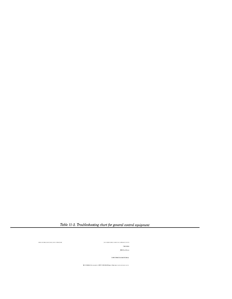
b. Electromagnetic devices. Table 11-2 lists some
only be used when and as recommended by the
manufacturer. If testing equipment can not be
of the more common troubles (with their causes and
grounded, special precautions should be taken. Also
remedies) encountered in general control equip-
refer to NEMA ICS 1.1.
ment.
Trouble
Cause
Course of action
CONTACTS:
1. Low voltage or current
Contact chatter.
Check voltage and current.
Improve the contact or use holding interlock.
2. Poor contact in control pickup circuit
Find out whether device is recommended for
3. Excessive chattering after jogging..
jogging service. If not, caution operator.
4. Broken pole shader or parts.
Replace defective part.
5. Contactor slams, thus opening interlock in
Increase wipe and pressure on interlock.
coil circuit.
11-8
|
 
|
|
|
||


