

Custom Search
|
|

|
||
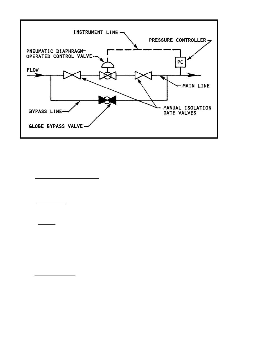 FIGURE 3-16.
Typical Pressure Reducing Station Configuration
tampered with, as when unauthorized persons shift the position of the weight
on the lever.
2.2 Pressure Regulating Valve. This is the secondary valve of the pressure
r e d u c i n g station. Its main purpose is to control and maintain the pressure
required by the steam-using equipment. Pressure regulating valves are of the
same construction as pressure reducing valves.
2 . 3 Relief Valve. This valve is used to protect low-pressure lines and
steam-using equipment from overpressure should the pressure reducing valve
f a i l to operate.
2 . 4 S t r a i n e r . Strainers are installed ahead of pressure reducing or pressure
r e g u l a t i n g valves. Strainers are used in piping systems to remove foreign
m a t e r i a l from the fluid. L o o s e dirt, rust, scale, or other loose foreign
matter may cause malfunctions and costly damage if allowed to enter vital
equipment. The screen of a strainer is usually constructed of a thin sheet of
b r o n z e , monel, or stainless steel. The screen or basket can be removed for
cleaning.
In some strainers a blowoff valve is provided to permit blowing out
f o r e i g n material while in service. F i g u r e 3-18 illustrates a pipe line
s t r a i n e r furnished with a connection for a blowoff valve.
2 . 5 Auxiliary Valves. Isolating gate valves are provided to remove from
service pressure reducing and pressure regulating valves. In large
installations, or where a continuous supply of steam must be assured, pressure
r e d u c i n g stations are provided with bypass valves installed parallel to the
3-52
|
 |
|
|
||


