

Custom Search
|
|

|
||
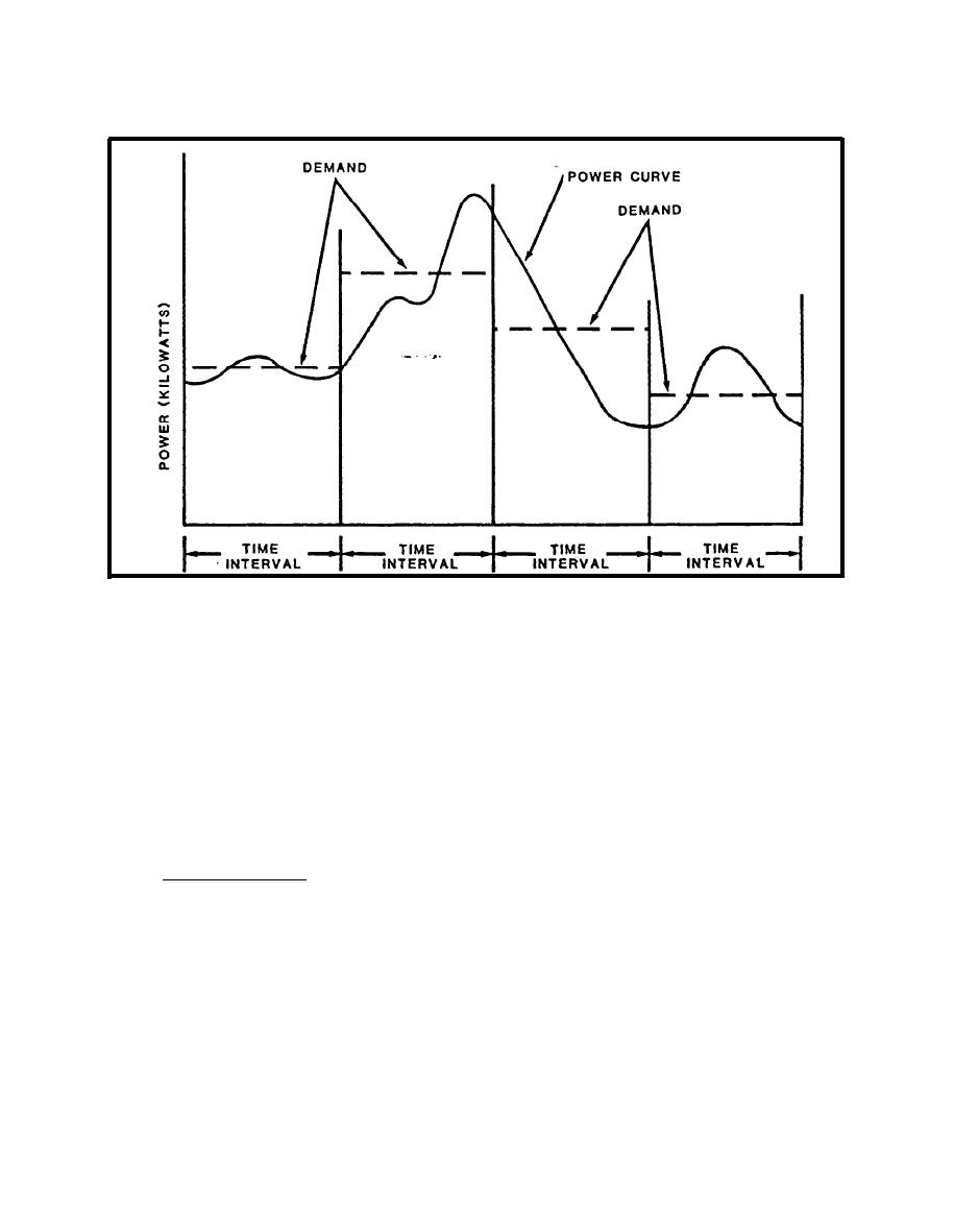 FIGURE 9-3.
Demand Chart
4. ELECTRIC METERING COMPONENTS. A wattmeter monitors the two basic
components of electrical power, current and voltage. Typical connection
is a high-resistance device and is always connected in parallel with a source
of power or load. The ammeter measures-current flowing-through a conductor is
a low-resistance device always connected in series with the source of power or
measures power flow from the source to the load. The potential coils are
connected in parallel and the current coils are connected in series with the
load. Typical connections for a single phase wattmeter is also shown in
Figure 9-4.
4.1 Watthour Meters. The watthour meter is a carefully calibrated induction
motor. It measures electrical energy by utilizing the interaction of fluxes
generated by current and voltage elements acting to produce eddy currents in
the rotor (disk). The eddy current flow produces lines of force which in turn
The speed that the disk turns depends upon the energy (watts) being measured.
Each revolution of the meter disk has a value in watt-hours. A constant
(Kh) represents the number of watthours per revolution. A register counts
revolutions and displays the count as kilowatthours (kWh).
9-9
|
 
|
|
|
||


