

Custom Search
|
|

|
||
 2.2 BASIC CONFIGURATION OF CLOSED-LOOP SYSTEMS
Closed-loop systems use a relatively small pump to move a non-freezing fluid
between the solar collectors and a heat exchanger. The heat exchanger, installed in
a heated space, transfers the heat from the non-freezing fluid to water.
This water is circulated between the heat exchanger and the storage tank by
another relatively small pump. The heat exchanger, pumps and storage tank are all
normally installed in a heated space.
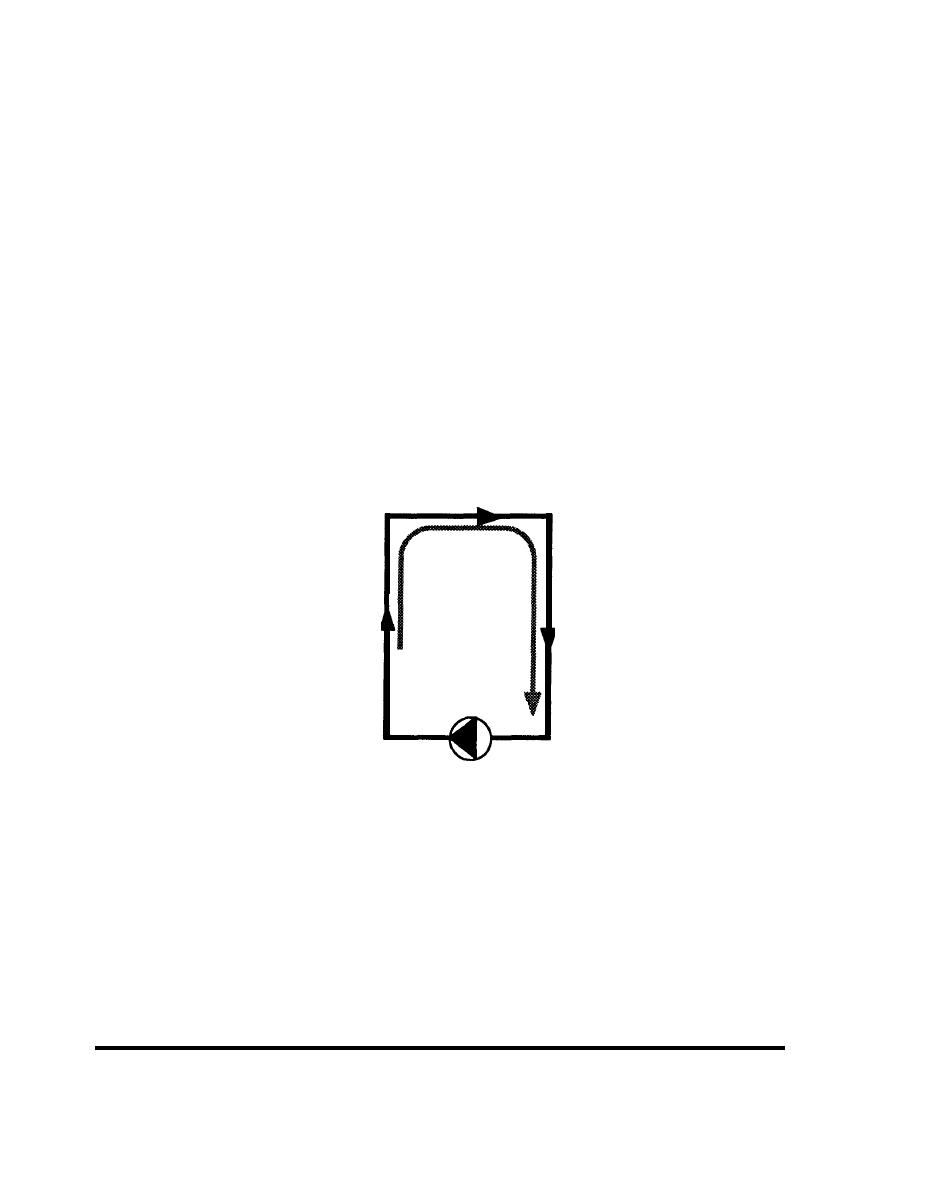
Pumps in a closed-loop system are relatively small because the piping loops they
serve are completely filled. Looking at the collector loop in Figure 2-10, you can see
that, like a siphon, the fluid falling down the return line will pull fluid up the feed line.
Put another way, the energy required to push fluid to the top of the collectors is
offset by gravity pulling it down the other side. The only energy the pump must
supply is that necessary to overcome the resistance due to the friction in the piping.
FIGURE 2-10
Fluid in a Loop.
The fluid falling down
the return line acts to
pull up the fluid in the
feed line. This works
as long as the loop is
completely filled.
CIRCULATING
PUMP
The pump moving the non-freezing solar fluid must be fitted with special seals and
gaskets compatible with the fluid being used. Heat exchanger gaskets and valve
seals must also be chosen carefully. Appendix E shows which materials are
appropriate for various fluids.
The pump circulating water must be of bronze or stainless steel construction, to
avoid corrosion and eventual leakage. The water tubes inside the heat exchanger
must also be made of materials appropriate for water, usually copper or brass.
OPERATION
14
2.2 CLOSED LOOP SYSTEMS
|
 
|
|
|
||


