

Custom Search
|
|

|
||
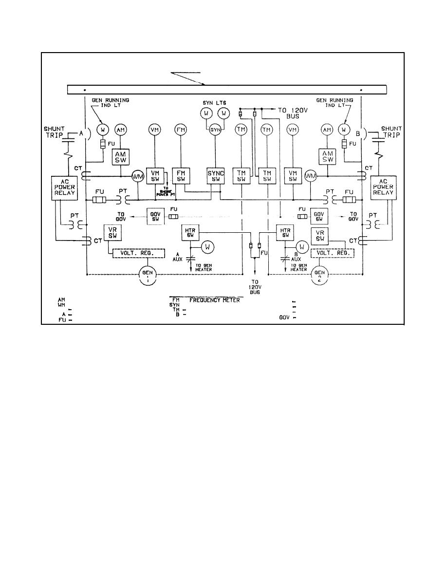 TM 5-685/NAVFAC MO-912
450 VOLTS, 3PH 60 CPS
G E N E R A T O R BUS
LEGEND
- AMMETER
-
VOLTAGE REGULATOR
VR
- SYNCHROSCOPE
POTENTIAL TRANSFORMER
PT
VM
TEMPERATURE METER
CURRENT TRANSFORMER
CT
GEN. CKT BREAKER
GE. CKT BREAKER
GOVERNOR
FUSE
Figure 5-2. Typical switchgear control circuitry, one-line diagram.
short-circuit protection of motor branch circuits
(1) Ratings. A PT is rated for the primary volt-
where motor overload or running protection is pro-
age along with the turns (step down) ratio to secure
vided by other elements.
120 VAC across the secondary.
(c) Non-automatic circuit interrupters have
(2) Application. The primary of potential trans-
no automatic overload or short circuit trip elements.
formers is connected either line-to-line or line-to-
These are used for manual switching and isolation.
neutral, and the current that flows through this
Other devices must be provided for short circuit and
winding produces a flux in the core. Since the core
overload protection.
links the primary and secondary windings, a volt-
age is induced in the secondary circuit (see fig 5-4).
former (PT) is an accurately wound, low voltage loss
The ratio of primary to secondary voltage is in pro-
instrument transformer having a fixed primary to
portion to the number of turns in the primary and
secondary "step down" voltage ratio. The PT is
secondary windings. This proportion produces 120
mounted in the high voltage enclosure and only the
volts at the secondary terminals when rated voltage
low voltage leads from the secondary winding are
is applied to the primary.
brought out to the metering and control panel. The
(3) Dot convention. A dot convention is used in
PT isolates the high voltage primary from the me-
figure 5-5. The dot convention makes use of a large
tering and control panel and from personnel. The
dot placed at one end of each of the two coils which
step down ratio produces about 120 VAC across the
are mutually coupled. A current entering the dotted
secondary when rated voltage is applied to the pri-
terminal of one coil produces an open-circuit voltage
mary. This permits the use of standard low voltage
between the terminals of the second coil. The volt-
meters (120 VAC full scale) for all high voltage cir-
age measured with a positive voltage reference at
cuit metering and control.
the dotted terminal of the second coil.
5-3
|
 
|
|
|
||


