

Custom Search
|
|

|
||
 TM 5-685/NAVFAC MO-912
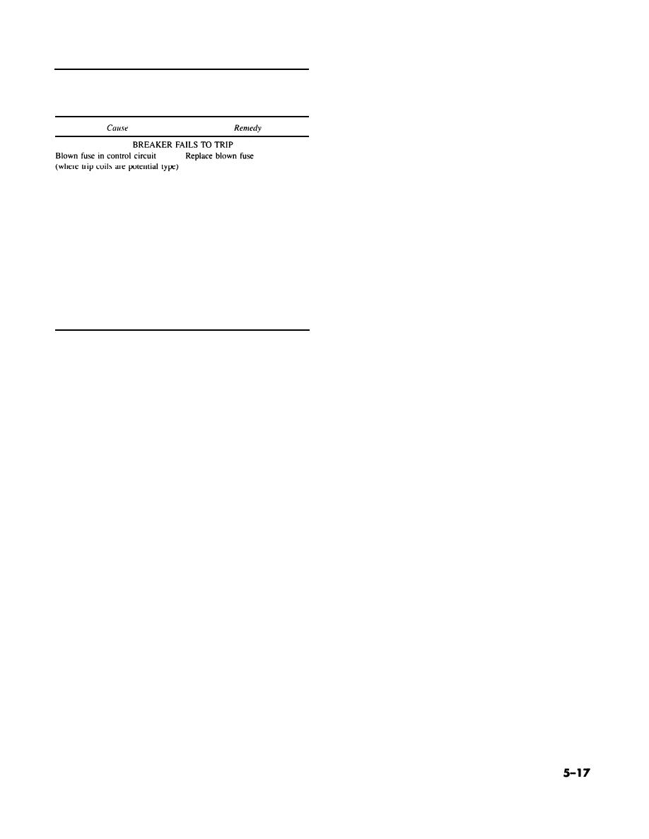
Table 5-2. Switchgear equipment
(4) Frequency. Frequency of alternating cur-
troubleshooting-Continued
rent is indicated on a frequency meter. The meter
scale is usually graduated in 50/60 Hertz.
Note
(5) Speed. Rotational speed of the prime mover
Refer to manufacturer's literature for specific information on
is indicated by a tachometer in revolutions per
individual equipment.
minute (rpm). Generating systems covered herein
usually use an impulse tachometer, including the
inductor and eddy current types. These tachometers
use a magnetic pick-up to sense speed.
(6) Temperature. Several temperature values
(including coolant, lubricating oil and exhaust) are
Faulty connections (loose or bro-
Repair faulty wiring, tighten all
usually required to assure safe prime mover opera-
ken wire) in trip circuit
binding screws to proper torque
tion. Each value is monitored by a sensing device
value
with a remote indicator or thermometer. The sens-
OIL CONTAMINATED
ing device can be thermocouple or a combination of
Carbonization from too many op-
Drain oil and filter, clean or re-
sensing bulb and capillary tube.
erations
place. Add fresh oil. Clean inside
(a) Thermocouple. A thermocouple consists of
of tank and all internal parts of
breaker; refer to manufacturer's
a pair of electrical conductors, each of different
instructions
metal, which are joined at the end adjacent to the
Condensation due to atmospheric
Same procedure as above
temperature to be measured. A thermal emf is pro-
conditions
duced at the junction of the conductors. The other
end of each conductor is connected to a voltmeter
Overheating
Eliminate cause of overheating
which measures and indicates the thermal emf.
5-7. Instrumentation.
(b) Sensing bulb and capillary tube. T h e
sensing bulb and capillary tube contain a specific
Switchgear instrumentation, based on the complex-
amount of liquid or gas whose pressure varies with
ity of the complete system, may include all or any
temperature. The variation appears on the ther-
combination of indicating, recording, and metering
mometer and represents the temperature of coolant,
instruments. Potential and current transformers
oil or exhaust.
are used to isolate instrument circuits from the
(7) Pressure. Pressure in the prime mover is
power circuit. Usually, the secondary winding of
indicated by sensing devices and remote gauges.
potential transformers is rated at 120 volts. Current
Usually a bourdon tube is used. The variation ap-
transformer output is 5 amperes.
pears on the gauge and represents lubricating oil or
a. Types of instrumentation. Instrumentation in-
other pressure. Other pressure values may be
cludes indicating and recording types.
shown on the system instrument panel depending
b. Application. Information related to instrument
on the type of prime mover and the overall system
transformer application is covered in paragraphs
requirements. These pressure values include start-
5-3b( 2) and 5-3c(2).
ing air, turbo boost, scavenging air, exhaust mani-
fold and fuel gas. Gauges or meters are used for
(1) Voltage. Voltage values are indicated by a
indication as required.
(2) Current. Current values are indicated by an
(8) Fuel level. Various methods are used for
fuel level measurement. Fuel in underground stor-
(3) Power. Power values are described as watts,
age tanks can be measured by immersing a cali-
brated dip stick in the tank. For day tanks, a glass
vars and power factor (refer to para 4-7 e for addi-
tional information).
sight-gauge or a float actuated gauge can be used to
(a) Watts. Watts or kilowatts (units of electric
measure the quantity of liquid fuel, Remote indica-
tors using pneumatic, electric or hydraulic devices
power) are indicated by a wattmeter.
(b) Vars. V a rs or kilovars (units of reactive
are also used.
power) are obtained by multiplying effective value
(9) Running time. The amount of time an aux-
iliary generating system operates is a required part
of current, effective value of voltage and the sine of
the angular phase difference between current and
of system record keeping. Time is usually recorded
voltage.
on a digital measuring device or counter located on
the system instrument panel. Usually the counter is
(c) Power factor. Power factor, the ratio of
used with electric or electronic circuitry. An electric
active power to apparent power, is displayed on a
power factor meter. The meter scale is usually
system usually has an AC synchronous motor that
graduated in percentage power factor.
is geared to the counter. Accuracy of motor and
|
 
|
|
|
||


