

Custom Search
|
|

|
||
 MIL-HDBK-1023/4
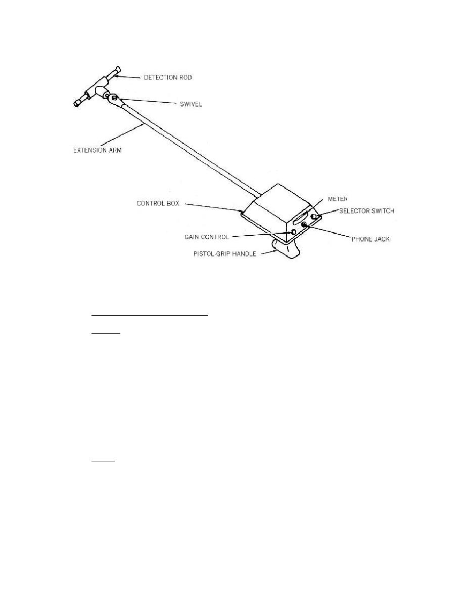
Figure 7
Cable Route Tracer
4.7
Impulse Generator/Proof Tester
4.7.1
General
a) The impulse generator/proof tester, Figure 8, is a compact signal unit contained in a
metal case. The test set is composed of an impulse generator and an internal DC power source.
The impulse generator contains a capacitor bank that is periodically charged from the DC source
and discharged into the cable to form the test voltage waveform.
b) In the impulse method of fault location, the impulse generator repeatedly applies a
high-voltage waveform to the defective cable. This waveform travels along the cable until it
reaches the fault. At the fault, the voltage causes significant current to pass through the return
path. This current, or its results, can be located and the fault position along the cable length can
be traced by an acoustic detector or a directional detector which are discussed in pars. 4.8 and
4.9.
4.7.2
Safety
a) The test set and the cable to which it is connected are a source of high-voltage
electrical energy, and all persons performing or assisting in the tests must use all practical safety
precautions to prevent contact with energized parts of the test equipment and associated circuits.
Persons actually engaged in the test must stand clear (by at least 3 feet (1 m)) of all parts of the
complete high-voltage circuit unless the test set is de-energized and all parts of the test circuit are
grounded. Any person not directly associated with the work must be kept away from test
activities by suitable barriers, barricades, or warnings.
27
|
 |
|
|
||


