
Custom Search
|
|

|
||
 MIL-HDBK-1023/4
maintenance staff, it is recommended that a contract be made with a qualified local repair shop
for periodic maintenance.
5.13
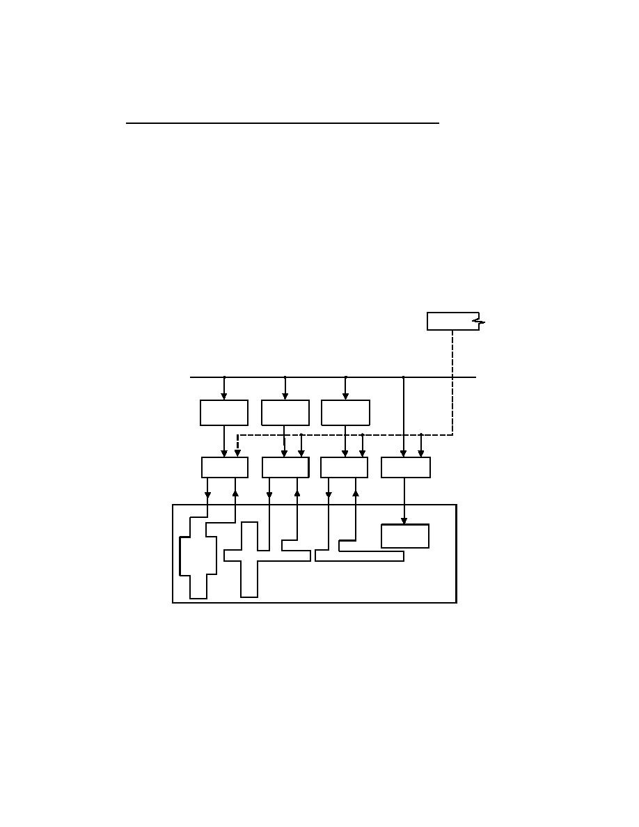
High Intensity Approach Lighting Systems (ALSF-1/ALSF-2). A typical layout of the
ALSF-1 and ALSF-2 systems are shown in Figures 18 and 19. To perform the PMIs contained
in Table 19, proceed as follows:
a) Daily Check. Check and record burned-out lamps.
b) Weekly checks
(1) Request tower personnel to turn on the system and cycle through each
brightness step from the remote control panel. If the system is equipped with air-to-ground radio
control, check each brightness step for proper operation. During the sequence, the maintenance
technician should be in a position to observe the system operation.
(2) Clean vegetation or obstructions from the front of all lights to ensure adequate
visibility. Use approved chemicals to help control the growth of vegetation around the lights.
PILOT RELAY
ASSY
TO
POWER
CIRCUIT
CIRCUIT
CIRCUIT
PROTECTIVE
PROTECTIVE
PROTECTIVE
DEVICES
DEVICES
DEVICES
SFL MASTER
REGULATOR
REGULATOR
REGULATOR
CONTROLLER
ASSY
ASSY
ASSY
SFL
APPROACH LIGHT AREA
Figure 19
ALSF-1 Block Diagram
76
|
 |
|
 |
||