

Custom Search
|
|

|
||
 MIL-HDBK-1023/4
(1) Figure 21 illustrates a regulator with the output on, a S1 cutout with the handle
installed and the load with no faults present.
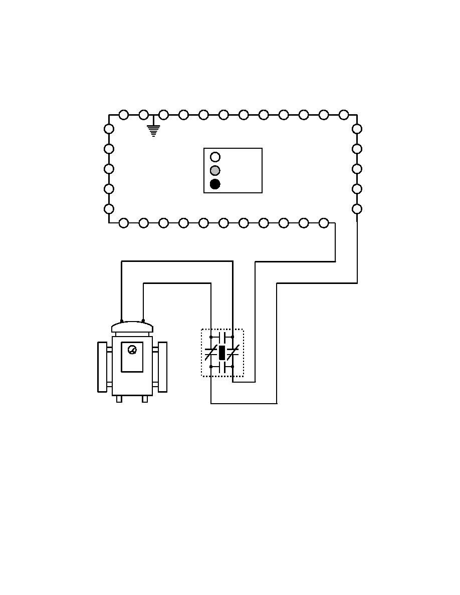
(2) Figure 22 illustrates the same equipment and load with a single ground on the
circuit. As illustrated, the lights are not affected by the single ground.
= ON
= DIM
= OFF
S1
ON
REGULATOR
Figure 22
Typical Load Circuit With S1 Cutout - Single Ground on Load
(3) Figure 23 illustrates the same equipment and load with two grounds on the
load. Note the intensity of the lights between the grounds has dimmed. This is a very common
condition the reader should be aware of. Driving the circuit will locate the bright to dim
transition in the fixtures, locating the grounds. The amount the lights dim will vary with the
resistance of the grounds. Low resistance grounds may conduct enough current to darken the
lamps entirely, while a high resistance ground may only dim the lamps enough to be detected
with an ammeter.
85
|
 |
|
|
||


