

Custom Search
|
|

|
||
 MIL-HDBK-1023/4
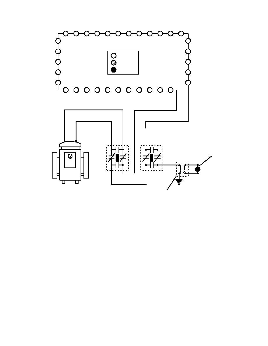
= ON
= DIM
= OFF
S1-B
S1-A
L1
L2
45 W EDGE LIGHT
ON
REGULATOR
GROUND
45 W ISOLATION
S1-A: TYPICAL INSTALLATION ON LOAD CIRCUIT.
S1-B: GROUND RETURN SWITCH WITH GROUND CURRENT INDICATING LIGHT.
SCHEMATIC ILLUSTRATES S1 HANDLES INSTALLED.
CAUTION: NOT RECOMMENDED FOR REGULATORS WITH 2400V OR 4160V INPUTS.
CAUTION: OPERATE S1 HANDLES WITH LOAD DE-ENERGIZED.
Figure 27
Regulator Connected to Typical S1 Cutout and Ground Return Switch With Ground Current
Indicating Circuit
(b) Figure 28 illustrates troubleshooting a single high resistance ground on the
load circuit. The illustration employs the "Ground Return Switch" and ground current indicating
circuit. Notice that the indicating light is on. The ground is located quickly by driving the
circuit and looking for the on/off light transition.
91
|
 |
|
|
||


