
Custom Search
|
|

|
||
 MIL-HDBK-1023/4
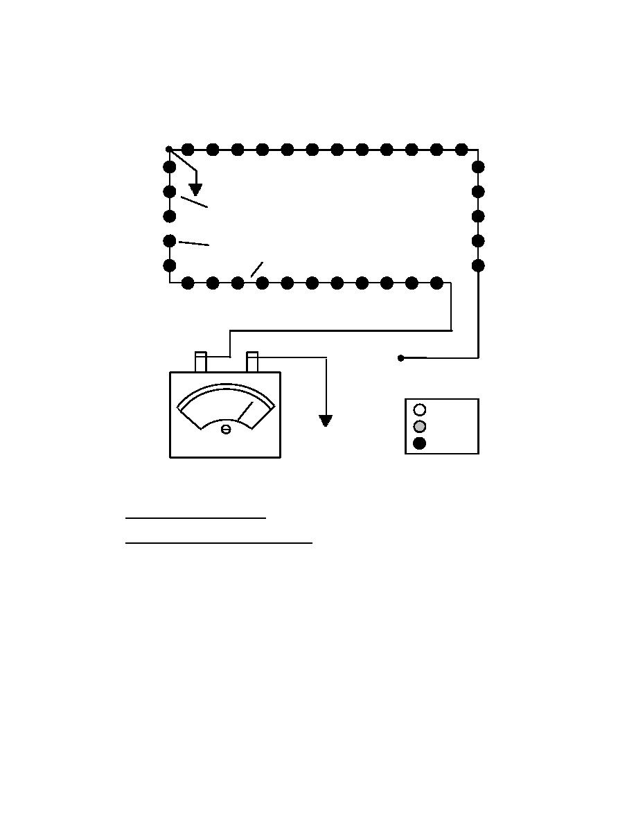
(e) We continue to divide the suspect section of the load circuit in half by
moving the inserted ground to location 4. Testing the circuit reveals that the circuit indicates an
open between the vault and location 4. However, we know from our previous test that the circuit
is good up to location 3. The open fault is located between location 3 and 4. See Figure 45.
INSERTED GROUND LOCATION 1
INSERTED GROUND LOCATION 4
OPEN
INSERTED GROUND LOCATION 3
INSERTED GROUND LOCATION 2
L1
L2
WIRENUT
<100M
0
= ON
GROUND
= DIM
= OFF
Figure 45
Sectional Isolation Method - Megger Confirms Open Between L1 and Inserted Ground
6.7
Overloads in Series Circuits
6.7.1
Isolating Overloads in Series Circuits. A circuit is overloaded when there are areas of
poor conductivity (high resistance) in the circuit loop, or when extra lights have been added to
the circuit and the total load is increased beyond the capacity of the regulator. An overload is
indicated when the regulator provides reduced current to the field circuit on all or only higher
steps, yet the regulator current is normal when the outputs are short circuited. If an overload is
indicated and the possibility of grounds on the circuit has not already been investigated, check
for grounds by following the procedure in par. 6.4.2.
a) If the insulating resistance of the circuit is not satisfactory, some combination of
grounds and an overload exist, such as high-resistance grounds on each side of an open or a high-
series resistance and ground fault. Use the cable test set, insulation resistance measurements, or
the intentional ground procedure to isolate the fault.
b) Symptom. Lights on suspected circuit don't reach full intensity. Current on output
of regulator is out of specification for high intensity. Usually the problem exists in higher
brightness levels only, but overloads may affect all brightness steps if severe enough.
112
|
 |
|
 |
||