

Custom Search
|
|

|
||
 (3) Berths and special cases assume ship speed of zero.
d. Ship motion vertical excursion of vessel from waves. Attachment (a) addresses ship motions only for
significant wave height. Each set of nomographs reflects the direction of the significant wave relative to
the direction of the CVN in transit; i.e., Following Seas are collinear with and in the same direction of
ship movement, Quartering Seas are those that approach the aft quarter of the ship at 45 degrees, Beam
Seas impact broadside to the ship, Bow Seas are those that approach the forward quarter of the ship at 45
degrees, and Head Seas are collinear with but opposite to the ship movement. The wave height and period
should be transformed to and through the channel entrance using local wave data or Army Corps of
Engineers reports entitled, "Wave Information Studies of U.S. Coastlines" (Studies 1-30).
(1) Outer channels -- use Hs for periods greater than 10 seconds with a 6 days/month recurrence interval
unless directed differently by the Activity. Exclude hurricane waves.
An example of this procedure is as follows:
(a) Determine the wave climatology. Using available data determine the significant wave height,
direction, and period. Transform waves into harbor based on shoaling, refraction, and
diffraction, etc.
(b) Based on local traffic and regulations, assume an average ship speed through channel; e.g. 14
knots.
(c) Using the calculated wave climatology, assumed ship speed, and the charts in Attachment B,
determine the predicted vertical ship motion for all applicable directions.
(2) Inner channels and berths use Hs = 0.
(3) Special cases use Hs for periods greater than 10 seconds with a 25 yr.
recurrence interval, unless directed differently by the Activity. Include hurricane waves if the berth is
expected to be occupied during that extreme event.
e. Clearance distance from the lowest point on the vessel to the design depth. For berths, turning basins,
and inner channels, Attachment (a) incorporates a 6 foot clearance to prevent ingestion of benthic biota.
This clearance when combined with installed discharge diffusers reduces the possibility of condenser
fouling. Additional studies may reduce the requirement and can be performed if funded. The designer
must collect all historical data available regarding fouling of condensers to ascertain the extent of the
problem. The NAVFAC Criteria Office is available to assist in analyzing this data. Notwithstanding, at
berths the designer must ensure that a minimum of 2 feet of clearance is provided at Extreme Low Water.
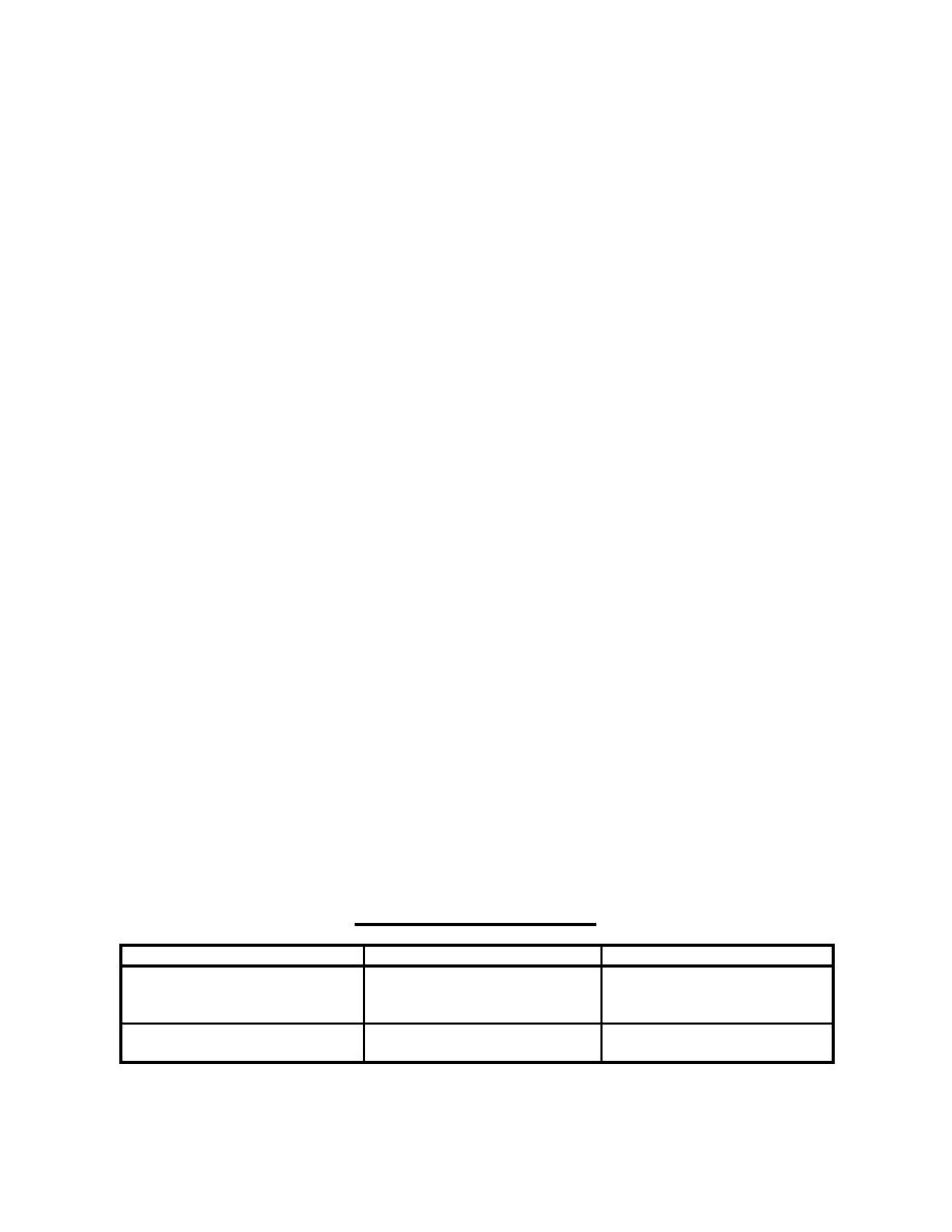
See table below for other categories:
RECOMMENDED CLEARANCES
LOCATION CATEGORY
SOFT BOTTOM
HARD BOTTOM
1. Outer channel
3.0 feet for 50 feet depth
4.0 feet for < 52 feet depth
4.4 feet for 54 feet depth
5.5 feet for > 58 feet depth
5.5 feet for > 58 feet depth
2. Special berths
6 feet (min.) coupled with
6 feet (min.) coupled with
discharge diffusers
discharge diffusers
7
|
 |
|
|
||


