

Custom Search
|
|

|
||
 MIL-HDBK-419A
2.3 SOIL RESISTIVITY.
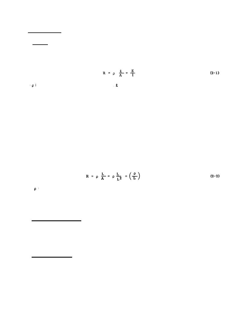
2.3.1 General. The resistivities of the soil and rock in which the earth electrode subsystem is buried,
constitute the basic constraint on the achievement of a low resistance contact with earth. The resistance of an
earth electrode subsystem can in general be calculated with formulas which are based upon the general
resistance formula.
where
is the resistivity of the conducting material, is the length of the path for current flow in the earth, A
is the cross-sectional area of the conducting path, I is the current into the electrode, and E is the voltage of the
electrode measured with respect to infinity. It will be shown later in this chapter that if the soil resistivity is
known, the resistance of the connection provided by the more common electrode configurations can be readily
determined.
The soils of the earth consist of solid particles and dissolved salts. Electrical current flows through the earth
primarily as ion movement; the ionic conduction is heavily influenced by the concentration and kinds of salts in
the moisture in the soil. Ionic disassociation occurs when salts are dissolved, and it is the movement of these
ions under the influence of electrical potential which enable the medium to conduct electricity.
Resistivity is defined in terms of the electrical resistance of a cube of homogeneous material. The resistance
of a homogeneous cube, as measured across opposite faces, is proportional to the resistivity and inversely
proportional to the length of one side of the cube. The resistance is
ohms
where
= resistivity of the material, ohms - (unit-of-length);
L = length of one side of the cube, (unit-of-length), and
A = area of one face of the cube, (unit-of-length)2.
Common units of resisitivity are ohm-cm and ohm-m.
2.3.2 Typical Resistivity Ranges. A broad variation of resistivity occurs as a function of soil types, and
classification of the types of soils at a potential site for earth electrodes is needed by the designer. Table 2-2
permits a quick estimate of soil resistivity, while Table 2-3 lists measured resistivity values from a variety of
sources. Tables 2-2 and 2-3 indicate that ranges of one or two orders of magnitude in values of resistivity for a
given soil type are to be expected.
2.3.3 Environmental Effects. In addition to the variation with soil types, the resistivity of a given type of soil
will vary several orders of magnitude with small changes in the moisture content, salt concentration, and soil
temperature. It is largely these variations in soil environment that cause the wide range of values for each soil
type noted in Tables 2-2 and 2-3. Figure 2-3 shows the variations observed in a particular soil as moisture,
salt, and temperature were changed. The curves are intended only to indicate trends -- another type of soil
would be expected to yield curves with similar shapes but different values.
2-7
|
 |
|
|
||


