
Custom Search
|
|

|
||
 MIL-HDBK-419A
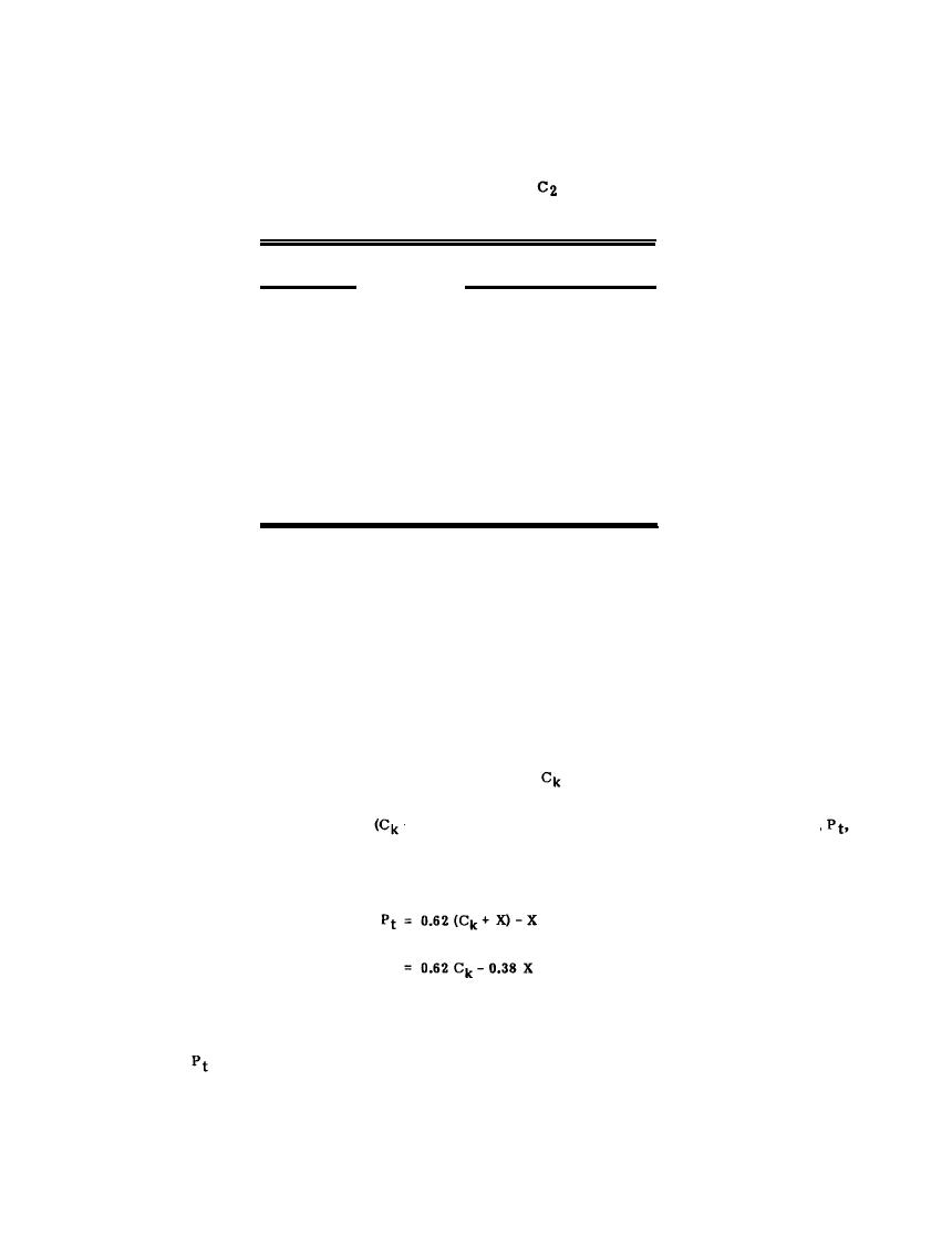
Table 2-6
Resistance Accuracy Versus Probe
Spacing
Accuracy
Probe Spacing
(percent)
90
5 x diagonal under test
95
10 x diagonal under test
98
25 x diagonal under test
99
50 x diagonal under test
On each curve the points corresponding to 62 percent of the distance to the current probe have been connected.
It is evident that as the current probe location is moved farther out, the 62 percent value is decreasing. The
true value of resistance can be estimated by extrapolating the connecting line to its asymptotic value. Because
none of the curves in Figure 2-18 level out, even the largest spacing of the current probe is evidently too small
for a direct reading of the resistance. Basic assumptions for the fall-of-potential measurement are that (1) the
electrode to be measured can be approximated as a hemisphere and (2) the connection to the earth electrode is
made at its electrical center. Since the location of the electrical center may not be known or may be
inaccessible, the connection is usually made at a convenient point at a distance X (Figure 2-19) from the
electrical center, D. The distance from the true center of the electrode to the current probe (assuming the
measurements are made on a radial from the electrical center) is + X. The use of 62 percent point on the
curves of Figure 2-18 to determine the resistance of the earth electrode should in reality correspond to a
position of the potential probe that is 0.62
+ X) from the true center (D). This means that the distance,
from the point of actual connection (O) to the system to the location at which the correct resistance to earth
exists will be
(2-50)
where
= Distance of potential probe from point of connection to electrode when the measured
resistance is the true value of resistance-to-earth for the electrode,
2-43
|
 |
|
 |
||