

Custom Search
|
|

|
||
 MIL-HDBK-419A
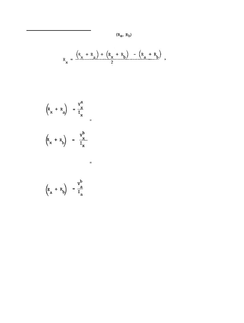
2.7.3 Three-Point (Triangulation) Method. In this method, illustrated in Figure 2-21 the resistances of the
electrode under test (Rx) and the auxiliary electrodes
are measured two at a time. The unknown
resistance is then computed from the formula.
(2-51)
where the terms in the parenthesis are the following measured resistances:
(2-52)
voltage drop from test electrode, X, to electrode A, divided by
current entering test electrode, X,
(2-51)
voltage drop from test electrode to electrode B, divided by
current into test electrode, X,
(2-52)
=
voltage drop from electrode A to electrode B, divided by current
entering electrode A.
For best accuracy, it is important to use auxiliary electrodes with resistances of the same order of magnitude
as the unknown. The series resistances may be measured either with a bridge or with a voltmeter and ammeter.
Either alternating or direct current may be used as the source of test current. For the three-point
measurement, the electrodes must be at some distance from each other; otherwise absurdities such as zero or
even negative resistances may arise in the calculations. In measuring a single 3 meter (10-foot) driven ground
rod, the distance between the three separate ground electrodes should be at least 5 meters (15 feet), with a
preferable spacing of 8 meters (25 feet) or more. For larger area grounds, which are presumable of lower
resistances, spacing on the order of the dimensions of the ground field is required as a minimum. This method is
most effective for measurement of single rods and is not recommended for multi-rod earth electrode
subsystems.
2-46
|
 |
|
|
||


