
Custom Search
|
|

|
||
 MIL-HDBK-419A
CHAPTER 5
GROUNDING OF SIGNAL REFERENCE SUBSYSTEM
5.1 INTRODUCTION.
Signal circuits are grounded and referenced to ground to (1) establish signal return paths between a source and a
load, (2) control static charge, or (3) provide fault protection. The desired goal is to accomplish each of these
three grounding functions in a manner that minimizes interference and noise.
If a truly zero impedance ground reference plane or bus could be realized, it could be utilized as the return path
for all currents -- power, control, audio and rf -- present within a system or complex. This ground reference
would simultaneously provide the necessary fault protection, static discharge, and signal returns. The closest
approximation to this ideal ground would be an extremely large sheet of a good conductor such as copper,
aluminum, or silver underlying the entire facility with large risers extending up to individual equipments. The
impedance of this network at the frequency of the signal being referenced is a function of conductor length,
resistance, inductance, and capacitance. When designing a ground system in which rf must be considered,
transmission line theory must be utilized.
5.2 CONDUCTOR CONSIDERATIONS.
5.2.1 Direct Current Resistance.
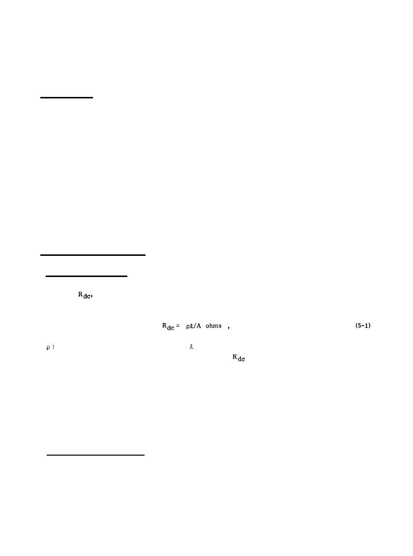
The resistance,
of a conductor of uniform cross section is proportional to the length and inversely
proportional to the cross-sectional area, that is
where is the resistivity of the conductor material,
is the length of the conductor in the direction of current
flow, and A is the cross-sectional area of the conductor. Values of
for the standard sizes of wire and cable
are given in Table 5-1. (For data on wire sizes not shown in this table, consult References 5-1 and 5-2.)
At dc, the resistance of the conductor is the controlling factor. Except for very unusual situations (such as
when the signal to be processed is very low in amplitude or where the interfacing equipments are very far apart
physically), an adequate ground can generally be realized for dc in a relatively economical manner utilizing low
resistivity materials such as copper and aluminum. Most systems, however, employ other than dc signals.
Therefore, the frequency-dependent properties of the conductors become important.
5.2.2 Alternating Current Impedance. The ac impedance of a conductor is composed of two parts: the ac
resistance and the reactance. Both the ac resistance and the reactance of a conductor vary with frequency as a
result of skin effect,
5-1
|
 |
|
 |
||