

Custom Search
|
|

|
||
 MIL-HDBK-419A
In addition, a floating ground system suffers from other limitations. For example, static charge buildup on the
isolated signal circuits is likely and may present a shock and a spark hazard. In particular, if the floated system
is located near high voltage power lines, static buildup is very likely. Further, in most modern electronic
facilities, all external sources of energy such as commercial power sources are referenced to earth grounds.
Thus, a danger with the floating system is that power faults to the signal system would cause the entire system
to rise to hazardous voltage levels relative to other conductive objects in the facility. Another danger is the
threat of flashover between the structure or cabinet and the signal system in the event of a lightning stroke to
the facility. Not being conductively coupled together, the structure could be elevated to a voltage high enough
relative to the signal ground to cause insulation breakdown and arcing. This system generally is not
recommended for C-E facilities.
Figure 5-11. Floating Signal Ground
5.3.2 Single-Point Ground. (For lower frequencies, 0-30 kHz up to 300 kHz)*
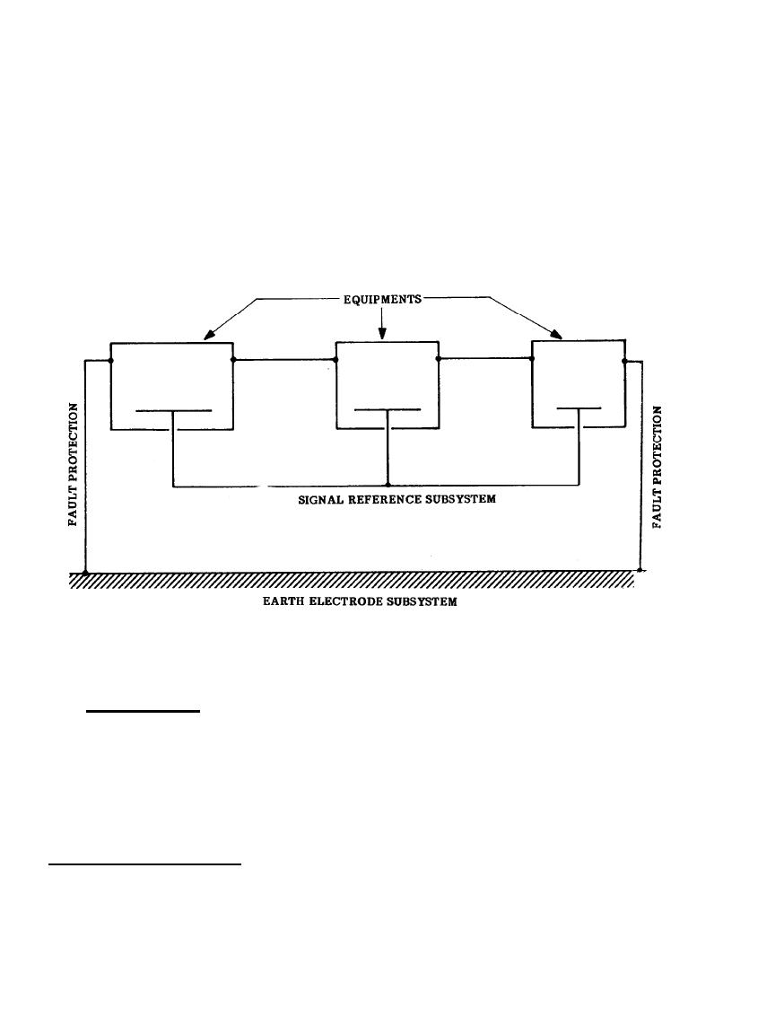
A second configuration for the signal ground network is the single-point approach illustrated in Figure 5-12.
With this configuration, the signal circuits are referenced to a single point, and this single point is then
connected to the facility ground. The ideal single-point signal ground network is one in which separate ground
conductors extend from one point on the facility ground to the return side of each of the numerous circuits
* Refer to 5.4.3 for definition of frequency limits.
5-19
|
 |
|
|
||


