

Custom Search
|
|

|
||
 MIL-HDBK-419A
higher frequencies because of large self-impedances. Further, because of stray capacitance between
conductors, single-point grounding essentially ceases to exist as the signal frequency is increased (5-10).
Because of the aforementioned reasons, single-point grounds are not recommended for use in communications
electronics facilities.
5.3.3 Multipoint Ground. (For higher frequencies, 30-300 kHz and above)
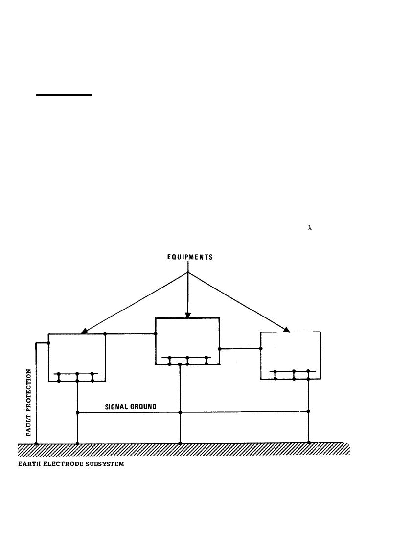
The multipoint ground illustrated in Figure 5-16 is the third configuration used for signal ground networks. The
multipoint ground utilizes many conductive paths from the earth electrode subsystem to various electronic
systems or subsystems within the facility. Within each subsystem, circuits and networks are multiply connected
to this ground network. Thus, in a facility, numerous parallel paths exist between any two points in the ground
network as shown in Figure 5-17.
Multipoint grounding frequently simplifies circuit construction inside complex equipments; it is the only
realistic method for the grounding of higher frequency signal circuits. This method of grounding permits
equipments employing coaxial cables to be more easily interfaced since the outer conductor of the coaxial cable
does not have to be floated relative to the equipment cabinet or enclosure. The multipoint grounding has the
disadvantage of exhibiting transmission line characteristics at rf frequencies. To be effective, a multipoint
ground system requires an equipotential ground plane whenever the conductors exceed 1/8
at the highest
frequency of concern (5-11).
Figure 5-16. Multipoint Ground Configuration
5-24
|
 |
|
|
||


