

Custom Search
|
|

|
||
 MIL-HDBK-419A
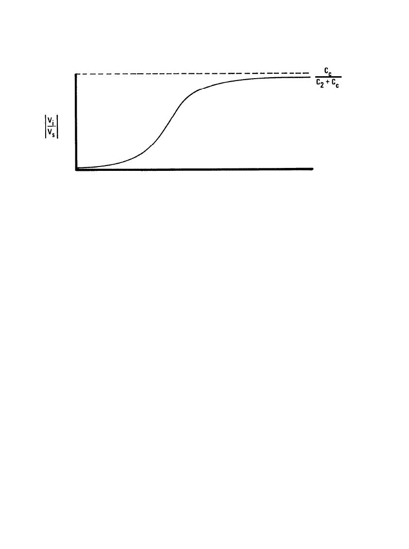
LOG f
Figure 6-11. Characteristic Voltage Transfer Curve for Capacitive Coupling
This method of visualizing radiation from a wire or antenna is illustrated for a dipole antenna in Figure 6-12.
Figure 6-12(a) shows a dipole when the charges are maximum at the ends of the antenna. As the current flow
reverses directions and the charges move back toward the center, the electric field lines collapse as in (b).
Since the field moves with a finite velocity, there is not enough time for all the field lines to return to the
antenna. When the ends of these lines meet at the center of the antenna and the charge on the antenna is zero,
the field lines that have not collapsed will close on themselves and continue to exist as closed loops as
illustrated in (c). The antenna charges move in the opposite direction as shown in (d), and the oppositely
directed electric field pushes away the previously detached loop as shown in (e). This procedure continues with
the fields in the opposite direction, and a cycle is completed when the fields near the antenna return to their
original state. These cycles repeat at the frequency of the applied signal, and an electromagnetic field
propagates outward from the antenna at the speed of light. Although only the electric field is illustrated, there
is an associated magnetic field in accordance with Maxwell's equations (6-l). The magnetic field consists of
concentric circles surrounding the antenna and expanding radially as the electric field propagates outward.
These outward propagating electric and magnetic fields represent energy flowing away from the antenna.
Therefore, the antenna radiates energy into the surrounding space.
In a reciprocal manner, wires and conductors located in a radiated field have currents induced in them and act
as receiving antennas for incident electromagnetic energy. These induced currents in the wires can then be
conducted into associated signal circuitry as interference (see Section 6.2.1). The amplitude of the resulting
interference depends on the strength of the electromagnetic field in the vicinity of the wire and on the
efficiency of the wire as an antenna. The strength of this field is a function of the distance from the radiating
wire, the efficiency of the radiating wire as an antenna, and the amplitude and frequency of the signal on the
radiating wire. The efficiency of a wire or other conductor as either a receiving or a radiating antenna is a
function of the length of the wire relative to the wavelength of the signal.
6-15
|
 |
|
|
||


