

Custom Search
|
|

|
||
 MIL-HDBK-419A
b.
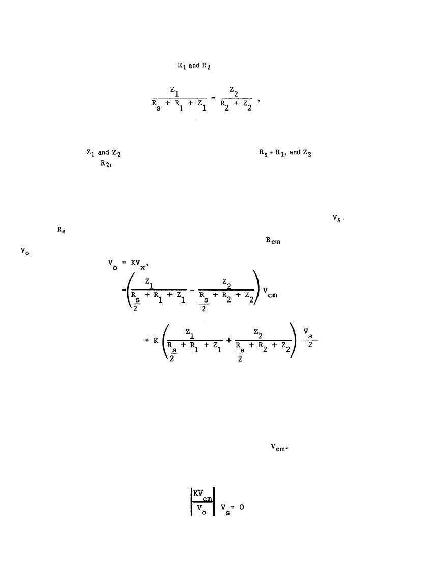
Balance the Two Amplifier Inputs - If
are manipulated such that
(6-22)
the common-mode noise voltage at the amplifier output terminals can be made to vanish.
- If Z1 is sufficiently large compared to
is sufficiently large
c.
Increase
compared to
then the common-mode noise voltage at the amplifier output terminals will be
diminished. This approach normally requires a differential amplifier with carefully shielded input
signal lines.
In the case of balanced signal sources or transducers, the basic circuit and equations differ from those given in
Figure 6-14 and by Equation 6-21. Figure 6-15 shows a balanced source with an output voltage
and output
r e s i s t a n c e connected to the two inputs of an amplifier. In this case, the center tap of the source is
connected to the ground reference terminal. As before, if it is assumed that
is small, it can be shown that
is given by
(6-23)
The same conclusions regarding the minimization of the common-mode noise component at the amplifier output
apply in this circuit as for the unbalanced source. However, in this case the amplifier must have a differential
input stage. Otherwise, one-half of the source would be shorted out. In Figure 6-14, the amplifier can have
single-ended or differential inputs.
The common-mode rejection (CMR) ratio of an amplifier is the gain of the amplifier (K) multiplied by the
common-mode noise voltage (Vcm) and divided by the amplifier output due to
The CMR ratio describes a
circuit's ability to avoid converting common-mode noise to normal-mode noise. Expressed as a positive
quantity, the CMR ratio is given by
(6-24)
CMR=
6-21
|
 |
|
|
||


