
Custom Search
|
|

|
||
 MIL-HDBK-419A
7.5.1 Resistance. The resistance of an indirect bond is equal to the sum of the intrinsic resistance of the
bonding conductor and the resistances of the metal-to-metal contacts at each end. The resistance of the strap
is determined by the resistivity of the material used and the dimensions of the strap. With typical straps, the
dc bond resistance is small. For example with a resistivity of 1.72 x
ohm-cm, (6.77 x
ohm-inches), a
copper conductor 2.5 cm, (1 inch) wide, 40 mils thick, and 0.3 meters (1 foot) long has a resistance of 0.2
milliohms. To this resistance will be added the sum of the dc resistances of the direct bonds at the ends of the
strap. With aluminum, copper, or brass straps, these resistances should be less than 0.1 milliohm with properly
made connections. If long straps are required, however, the resistance of the conductor can be significant (see,
for example Table 5-1).
7.5.2 Frequency Effects.
7.5.2.1 Skin Effect. Because high conductivity materials attenuate radio frequencies rapidly, high frequency
currents do not penetrate into conductors very far, i.e., they tend to stay near the surface. At frequencies
where this effect becomes significant the ac resistance of the bond strap can differ significantly from its dc
value. For a detailed discussion of skin effect, see Section 5.2.2.1.
7.5.2.2 Bond Reactance.
The geometrical configuration of the bonding conductor and the physical relationship between objects being
bonded introduce reactive components into the impedance of the bond. The strap itself exhibits an inductance
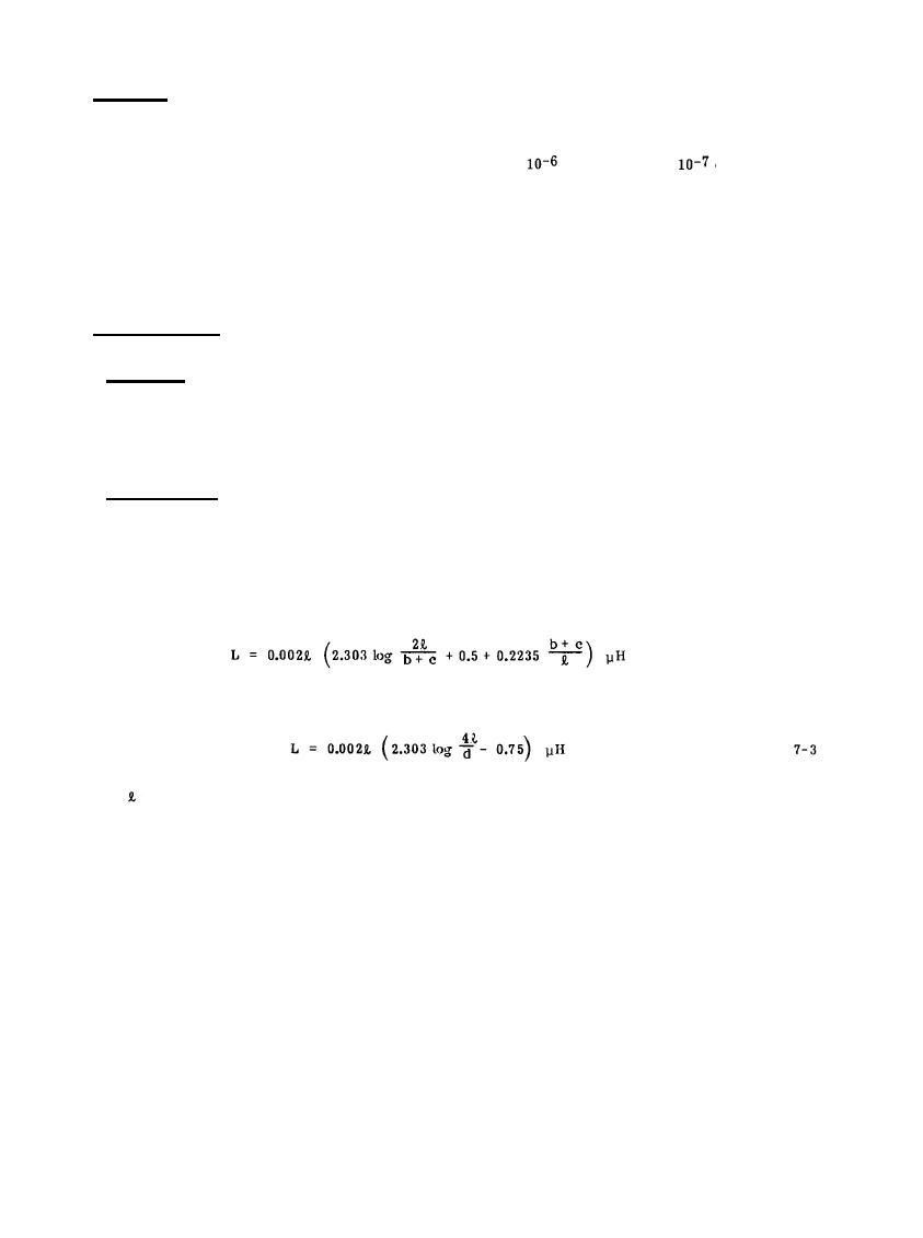
that is related to its dimensions. For a straight, flat strap of nonmagnetic metal, the inductance in
microhenries is given by
(7-2)
or, for a wire of circular cross section, by
where
= length in cm,
b = width of the strap in cm
c = thickness of the strap in cm, and
d = diameter of the wire in cm.
Table 7-3 shows the calculated inductance, using Equation (7-2), of a nonmagnetic rectangular strap, 6 inches
(15.2 cm) long. Table 7-4 compares the inductance of 6, 12, and 36 inch lengths of 0.05 inch (1.27 mm) thick
straps while Table 7-5 tabulates the inductance of 6, 12, and 36 inch lengths of selected standard size cables
from No. 14 AWG to 4/0 AWG. The inductive reactance of the straps tabulated in Tables 7-4 and 7-5 is plotted
in Figure 7-10 for frequencies up to 100 MHz.
7-19
|
 |
|
 |
||