
Custom Search
|
|

|
||
 MIL-HDBK-419A
8.2 BASIC SHIELDING THEORY.
The shielding effectiveness of an equipment or subassembly enclosure depends upon a number of parameters,
the most notable of which are the frequency and impedance of the impinging wave, the intrinsic characteristics
of the shield materials, and the numbers and shapes of shield discontinuities. The effectiveness of a shield is
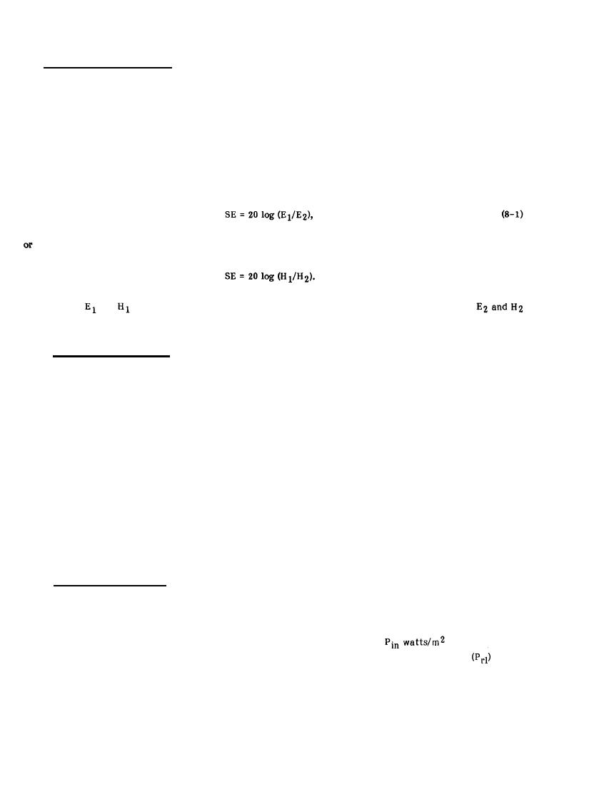
specified in terms of the reduction of EM field strength caused by the shield. The shielding effectiveness (SE) is
defined as the ratio of the field strength without the shield present to the field strength with the shield in
place. Because of the wide ranges in this ratio, it is common practice to express the shielding effectiveness in
decibels:
(8-2)
The variables
and
are the electric and magnetic field strengths without the shield present, and
are those with the shield in place.
8.2.1 Oppositely Induced Fields. A shielding action occurs whenever an electromagnetic wave encounters a
metal surface. Part of the wave energy is reflected back toward the source, part is dissipated in the metal, and
the remainder propagates beyond the metal. This shielding effect can be visualized as being the result of the
incoming electric and magnetic fields inducing charges at the surface of the shield and a current flow within
the shield, respectively. The induced charges and currents are of such a polarity and direction that their
associated electric and magnetic fields oppose the incident fields, thus reducing the EM fields beyond the
shield. Although this concept of the shielding theory does not lend itself to efficient calculation of the degree
of shielding provided by a particular shield, it does provide a useful physical picture of shielding. For example,
it can be seen from this viewpoint that shielding effectiveness would be reduced more if the shield were cut so
as to interfere with the induced current flow than if it were cut along the line of current flow. Thus, if a plane
EM wave is incident upon a conducting shield with a very long slit, more energy will be transmitted through the
slit if the electric field vector is perpendicular to the slit than if it is parallel to the slit (see Figure 8-1). This
is true because the EM boundary conditions (8-1) require that the induced shield current flow be perpendicular
to the incoming magnetic field vector (and thus parallel to the electric field vector).
8.2.2 Transmission Line Analogy. The shielding theory most applicable to engineering calculations is based
upon an analogy with transmission line theory. According to the planewave theory developed by Schelkunoff
(8-1), an electromagnetic shield transmits EM waves whose fronts coincide with the shielding boundary
configuration in a manner mathematically analogous to that in which a two-wire transmission line transmits
electrical current and voltage. Consider an incident EM wave with a power of
impinging upon a
flat shield as in Figure 8-2. When the wave encounters the first surface of the shield, a portion
of the
8-2
|
 |
|
 |
||